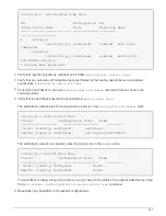
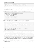

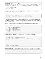

mcc1A::> metrocluster operation show
Operation: heal-root-aggregates
State: successful
Start Time: 7/29/2016 20:54:41
End Time: 7/29/2016 20:54:42
Errors: -
8. On the impaired controller module, disconnect the power supplies.
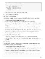
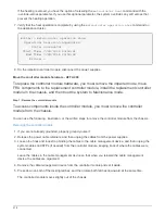
Move and replace hardware - AFF A400
Step 1: Remove the controller modules
To replace the chassis, you must remove the controller modules from the old chassis.
1. If you are not already grounded, properly ground yourself.
2. Release the power cable retainers, and then unplug the cables from the power supplies.
3. Loosen the hook and loop strap binding the cables to the cable management device, and then unplug the
system cables and SFPs (if needed) from the controller module, keeping track of where the cables were
connected.
Leave the cables in the cable management device so that when you reinstall the cable management
device, the cables are organized.
4. Remove and set aside the cable management devices from the left and right sides of the controller module.
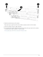
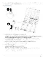
5. Press down on both of the locking latches, and then rotate both latches downward at the same time.
The controller module moves slightly out of the chassis.
6. Slide the controller module out of the chassis.
Make sure that you support the bottom of the controller module as you slide it out of the chassis.
7. Set the controller module aside in a safe place, and repeat these steps for the other controller module in
the chassis.
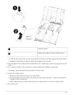
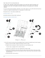
Step 2: Move the fans
To move the fan modules to the replacement chassis when replacing the chassis, you
must perform a specific sequence of tasks.
1. If you are not already grounded, properly ground yourself.
2. Remove the bezel (if necessary) with two hands, by grasping the openings on each side of the bezel, and
then pulling it toward you until the bezel releases from the ball studs on the chassis frame.
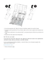
3. Press down the release latch on the fan module cam handle, and then rotate the cam handle downward.
The fan module moves a little bit away from the chassis.
4. Pull the fan module straight out from the chassis, making sure that you support it with your free hand so
509
Summary of Contents for AFF A700
Page 4: ...AFF and FAS System Documentation 1...
Page 208: ...3 Close the controller module cover and tighten the thumbscrew 205...
Page 248: ...2 Close the controller module cover and tighten the thumbscrew 245...
Page 308: ...Power supply Cam handle release latch Power and Fault LEDs Cam handle 305...
Page 381: ...Power supply Cam handle release latch Power and Fault LEDs Cam handle 378...
Page 437: ...1 Locate the DIMMs on your controller module 434...
Page 605: ...602...
Page 1117: ...3 Close the controller module cover and tighten the thumbscrew 1114...
Page 1157: ...2 Close the controller module cover and tighten the thumbscrew 1154...
Page 1228: ...Power supply Cam handle release latch Power and Fault LEDs Cam handle 1225...
Page 1300: ...Power supply Cam handle release latch Power and Fault LEDs Cam handle 1297...
Page 1462: ...Installing SuperRail to round hole four post rack 1459...
Page 1602: ...1599...
Page 1630: ...1627...
Page 1634: ...Orange ring on horizontal bracket Cable chain 1631...
Page 1645: ...Guide rail 1642...
Page 1669: ...Attention LED light on 1666...