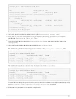
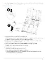
b. Locate the corresponding DIMM slot on the replacement controller module.
c. Make sure that the DIMM ejector tabs on the DIMM socket are in the open position, and then insert the
DIMM squarely into the socket.
The DIMMs fit tightly in the socket, but should go in easily. If not, realign the DIMM with the socket and
reinsert it.
d. Visually inspect the DIMM to verify that it is evenly aligned and fully inserted into the socket.
e. Repeat these substeps for the remaining DIMMs.
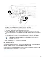
5. Plug the NVDIMM battery into the motherboard.
Make sure that the plug locks down onto the controller module.
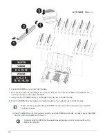
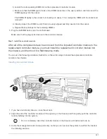
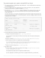
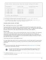
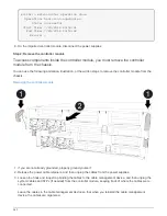
Step 7: Install the controller module
After all of the components have been moved from the impaired controller module to the
replacement controller module, you must install the replacement controller module into
the chassis, and then boot it to Maintenance mode.
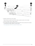
You can use the following animation, illustration, or the written steps to install the replacement controller
module in the chassis.
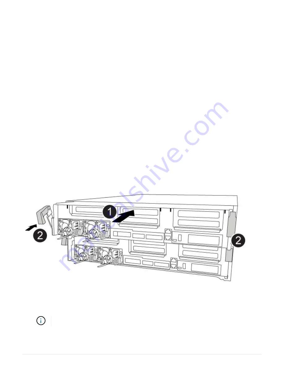
Installing the controller module
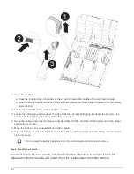
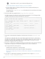
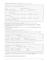
1. If you have not already done so, close the air duct.
2. Align the end of the controller module with the opening in the chassis, and then gently push the controller
module halfway into the system.
Do not completely insert the controller module in the chassis until instructed to do so.
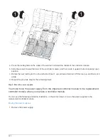
3. Cable the management and console ports only, so that you can access the system to perform the tasks in
the following sections.
527
Summary of Contents for AFF A700
Page 4: ...AFF and FAS System Documentation 1...
Page 208: ...3 Close the controller module cover and tighten the thumbscrew 205...
Page 248: ...2 Close the controller module cover and tighten the thumbscrew 245...
Page 308: ...Power supply Cam handle release latch Power and Fault LEDs Cam handle 305...
Page 381: ...Power supply Cam handle release latch Power and Fault LEDs Cam handle 378...
Page 437: ...1 Locate the DIMMs on your controller module 434...
Page 605: ...602...
Page 1117: ...3 Close the controller module cover and tighten the thumbscrew 1114...
Page 1157: ...2 Close the controller module cover and tighten the thumbscrew 1154...
Page 1228: ...Power supply Cam handle release latch Power and Fault LEDs Cam handle 1225...
Page 1300: ...Power supply Cam handle release latch Power and Fault LEDs Cam handle 1297...
Page 1462: ...Installing SuperRail to round hole four post rack 1459...
Page 1602: ...1599...
Page 1630: ...1627...
Page 1634: ...Orange ring on horizontal bracket Cable chain 1631...
Page 1645: ...Guide rail 1642...
Page 1669: ...Attention LED light on 1666...


