
You will connect the rest of the cables to the controller module later in this procedure.
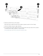
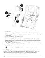
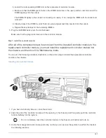
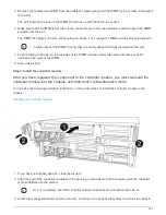
4. Complete the installation of the controller module:
a. Plug the power cord into the power supply, reinstall the power cable locking collar, and then connect
the power supply to the power source.
b. Using the locking latches, firmly push the controller module into the chassis until the locking latches
begin to rise.
Do not use excessive force when sliding the controller module into the chassis to avoid
damaging the connectors.
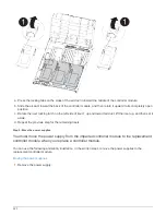
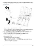
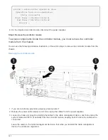
c. Fully seat the controller module in the chassis by rotating the locking latches upward, tilting them so
that they clear the locking pins, gently push the controller all the way in, and then lower the locking
latches into the locked position.
The controller module begins to boot as soon as it is fully seated in the chassis. Be prepared to
interrupt the boot process.
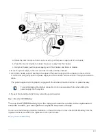
d. If you have not already done so, reinstall the cable management device.
e. Interrupt the normal boot process and boot to LOADER by pressing
Ctrl-C
.
If your system stops at the boot menu, select the option to boot to LOADER.
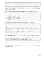
f. At the LOADER prompt, enter
bye
to reinitialize the PCIe cards and other components.
g. Interrupt the boot process and boot to the LOADER prompt by pressing
Ctrl-C
.
If your system stops at the boot menu, select the option to boot to LOADER.
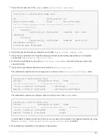
Restore and verify the system configuration - AFF A400
After completing the hardware replacement and booting to Maintenance mode, you verify
the low-level system configuration of the replacement controller and reconfigure system
settings as necessary.
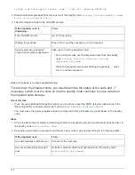
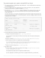
Step 1: Set and verify system time after replacing the controller
You should check the time and date on the replacement controller module against the
healthy controller module in an HA pair, or against a reliable time server in a stand-alone
configuration. If the time and date do not match, you must reset them on the replacement
controller module to prevent possible outages on clients due to time differences.
About this task
It is important that you apply the commands in the steps on the correct systems:
• The
replacement
node is the new node that replaced the impaired node as part of this procedure.
• The
healthy
node is the HA partner of the
replacement
node
Steps
528
Summary of Contents for AFF A700
Page 4: ...AFF and FAS System Documentation 1...
Page 208: ...3 Close the controller module cover and tighten the thumbscrew 205...
Page 248: ...2 Close the controller module cover and tighten the thumbscrew 245...
Page 308: ...Power supply Cam handle release latch Power and Fault LEDs Cam handle 305...
Page 381: ...Power supply Cam handle release latch Power and Fault LEDs Cam handle 378...
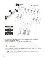
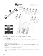
Page 437: ...1 Locate the DIMMs on your controller module 434...
Page 605: ...602...
Page 1117: ...3 Close the controller module cover and tighten the thumbscrew 1114...
Page 1157: ...2 Close the controller module cover and tighten the thumbscrew 1154...
Page 1228: ...Power supply Cam handle release latch Power and Fault LEDs Cam handle 1225...
Page 1300: ...Power supply Cam handle release latch Power and Fault LEDs Cam handle 1297...
Page 1462: ...Installing SuperRail to round hole four post rack 1459...
Page 1602: ...1599...
Page 1630: ...1627...
Page 1634: ...Orange ring on horizontal bracket Cable chain 1631...
Page 1645: ...Guide rail 1642...
Page 1669: ...Attention LED light on 1666...


