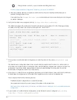


If the giveback is vetoed, you can consider overriding the vetoes.
Find the High-Availability Configuration Guide for your version of ONTAP 9
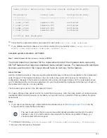
b. After the giveback has been completed, confirm that the HA pair is healthy and that takeover is
possible: storage failover show
The output from the
storage failover show
command should not include the System ID changed
on partner message.
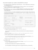
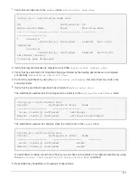
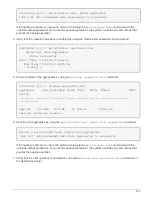
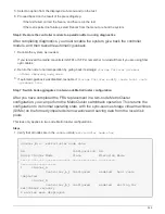
6. Verify that the disks were assigned correctly:
storage disk show -ownership
The disks belonging to the
replacement
node should show the new system ID. In the following example,
the disks owned by node1 now show the new system ID, 1873775277:
node1> storage disk show -ownership
Disk Aggregate Home Owner DR Home Home ID Owner ID DR Home ID
Reserver Pool
----- ------ ----- ------ -------- ------- ------- -------
--------- ---
1.0.0 aggr0_1 node1 node1 - 1873775277 1873775277 -
1873775277 Pool0
1.0.1 aggr0_1 node1 node1 1873775277 1873775277 -
1873775277 Pool0
.
.
.
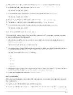
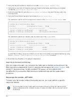
7. If the system is in a MetroCluster configuration, monitor the status of the node:
metrocluster node
show
The MetroCluster configuration takes a few minutes after the replacement to return to a normal state, at
which time each node will show a configured state, with DR Mirroring enabled and a mode of normal. The
metrocluster node show -fields node-systemid command output displays the old system ID until the
MetroCluster configuration returns to a normal state.
8. If the node is in a MetroCluster configuration, depending on the MetroCluster state, verify that the DR home
ID field shows the original owner of the disk if the original owner is a node on the disaster site.
This is required if both of the following are true:
◦
The MetroCluster configuration is in a switchover state.
◦
the
replacement
node is the current owner of the disks on the disaster site.
9. If your system is in a MetroCluster configuration, verify that each node is configured:
metrocluster
node show - fields configuration-state
532
Summary of Contents for AFF A700
Page 4: ...AFF and FAS System Documentation 1...
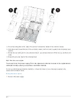
Page 208: ...3 Close the controller module cover and tighten the thumbscrew 205...
Page 248: ...2 Close the controller module cover and tighten the thumbscrew 245...
Page 308: ...Power supply Cam handle release latch Power and Fault LEDs Cam handle 305...
Page 381: ...Power supply Cam handle release latch Power and Fault LEDs Cam handle 378...
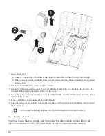
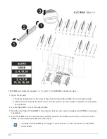
Page 437: ...1 Locate the DIMMs on your controller module 434...
Page 605: ...602...
Page 1117: ...3 Close the controller module cover and tighten the thumbscrew 1114...
Page 1157: ...2 Close the controller module cover and tighten the thumbscrew 1154...
Page 1228: ...Power supply Cam handle release latch Power and Fault LEDs Cam handle 1225...
Page 1300: ...Power supply Cam handle release latch Power and Fault LEDs Cam handle 1297...
Page 1462: ...Installing SuperRail to round hole four post rack 1459...
Page 1602: ...1599...
Page 1630: ...1627...
Page 1634: ...Orange ring on horizontal bracket Cable chain 1631...
Page 1645: ...Guide rail 1642...
Page 1669: ...Attention LED light on 1666...