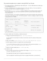


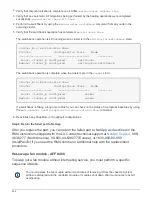


5. Select an option from the displayed sub-menu and run the test.
6. Proceed based on the result of the preceding step:
◦
If the test failed, correct the failure, and then rerun the test.
◦
If the test reported no failures, select Reboot from the menu to reboot the system.
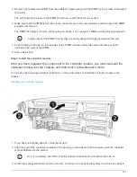
Step 6: Restore the controller module to operation after running diagnostics
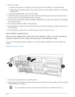
After completing diagnostics, you must recable the system, give back the controller
module, and then reenable automatic giveback.
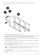
1. Recable the system, as needed.
If you removed the media converters (QSFPs or SFPs), remember to reinstall them if you are using fiber
optic cables.
2. Return the node to normal operation by giving back its storage:
storage failover giveback
-ofnode
impaired_node_name
3. If automatic giveback was disabled, reenable it:
storage failover modify -node local -auto
-giveback true
Step 7: Switch back aggregates in a two-node MetroCluster configuration
After you have completed the FRU replacement in a two-node MetroCluster
configuration, you can perform the MetroCluster switchback operation. This returns the
configuration to its normal operating state, with the sync-source storage virtual machines
(SVMs) on the formerly impaired site now active and serving data from the local disk
pools.
This task only applies to two-node MetroCluster configurations.
Steps
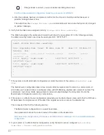
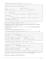
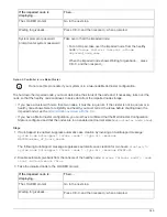
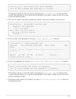
1. Verify that all nodes are in the
enabled
state:
metrocluster node show
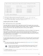
cluster_B::> metrocluster node show
DR Configuration DR
Group Cluster Node State Mirroring Mode
----- ------- -------------- -------------- ---------
--------------------
1 cluster_A
controller_A_1 configured enabled heal roots
completed
cluster_B
controller_B_1 configured enabled waiting for
switchback recovery
2 entries were displayed.
545
Summary of Contents for AFF A700
Page 4: ...AFF and FAS System Documentation 1...
Page 208: ...3 Close the controller module cover and tighten the thumbscrew 205...
Page 248: ...2 Close the controller module cover and tighten the thumbscrew 245...
Page 308: ...Power supply Cam handle release latch Power and Fault LEDs Cam handle 305...
Page 381: ...Power supply Cam handle release latch Power and Fault LEDs Cam handle 378...
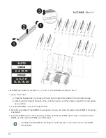
Page 437: ...1 Locate the DIMMs on your controller module 434...
Page 605: ...602...
Page 1117: ...3 Close the controller module cover and tighten the thumbscrew 1114...
Page 1157: ...2 Close the controller module cover and tighten the thumbscrew 1154...
Page 1228: ...Power supply Cam handle release latch Power and Fault LEDs Cam handle 1225...
Page 1300: ...Power supply Cam handle release latch Power and Fault LEDs Cam handle 1297...
Page 1462: ...Installing SuperRail to round hole four post rack 1459...
Page 1602: ...1599...
Page 1630: ...1627...
Page 1634: ...Orange ring on horizontal bracket Cable chain 1631...
Page 1645: ...Guide rail 1642...
Page 1669: ...Attention LED light on 1666...


