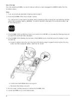

Make sure that the plug locks down onto the controller module.
13. Close the controller module cover.
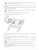
Step 4: Reinstall the controller module
After you replace components in the controller module, reinstall it into the chassis.
1. If you are not already grounded, properly ground yourself.
2. If you have not already done so, replace the cover on the controller module.
3. Align the end of the controller module with the opening in the chassis, and then gently push the controller
module halfway into the system.
Do not completely insert the controller module in the chassis until instructed to do so.
4. Recable the system, as needed.
If you removed the media converters (QSFPs or SFPs), remember to reinstall them if you are using fiber
optic cables.
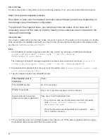
5. Complete the reinstallation of the controller module:
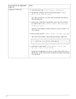
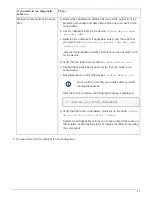
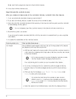
If your system is in…
Then perform these steps…
An HA pair
The controller module begins to boot as soon as it is fully seated in the chassis.
Be prepared to interrupt the boot process.
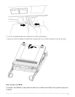
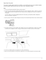
a. With the cam handle in the open position, firmly push the controller module in
until it meets the midplane and is fully seated, and then close the cam handle
to the locked position.
Do not use excessive force when sliding the controller module
into the chassis to avoid damaging the connectors.
The controller begins to boot as soon as it is seated in the chassis.
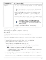
b. If you have not already done so, reinstall the cable management device.
c. Bind the cables to the cable management device with the hook and loop
strap.
d. When you see the message
Press Ctrl-C for Boot Menu
, press
Ctrl-C
to interrupt the boot process.
If you miss the prompt and the controller module boots to
ONTAP, enter
halt
, and then at the LOADER prompt enter
boot_ontap
, press
Ctrl-C
when prompted, and then boot to
Maintenance mode.
e. Select the option to boot to Maintenance mode from the displayed menu.
54
Summary of Contents for AFF A700
Page 4: ...AFF and FAS System Documentation 1...
Page 208: ...3 Close the controller module cover and tighten the thumbscrew 205...
Page 248: ...2 Close the controller module cover and tighten the thumbscrew 245...
Page 308: ...Power supply Cam handle release latch Power and Fault LEDs Cam handle 305...
Page 381: ...Power supply Cam handle release latch Power and Fault LEDs Cam handle 378...
Page 437: ...1 Locate the DIMMs on your controller module 434...
Page 605: ...602...
Page 1117: ...3 Close the controller module cover and tighten the thumbscrew 1114...
Page 1157: ...2 Close the controller module cover and tighten the thumbscrew 1154...
Page 1228: ...Power supply Cam handle release latch Power and Fault LEDs Cam handle 1225...
Page 1300: ...Power supply Cam handle release latch Power and Fault LEDs Cam handle 1297...
Page 1462: ...Installing SuperRail to round hole four post rack 1459...
Page 1602: ...1599...
Page 1630: ...1627...
Page 1634: ...Orange ring on horizontal bracket Cable chain 1631...
Page 1645: ...Guide rail 1642...
Page 1669: ...Attention LED light on 1666...


