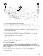

The riser raises up slightly from the controller module.
d. Lift the riser up straight up and set it aside on a stable flat surface,
2. Remove the PCIe card from the riser:
a. Turn the riser so that you can access the PCIe card.
b. Press the locking bracket on the side of the PCIe riser, and then rotate it to the open position.
c. For risers 2 and 3 only, swing the side panel up.
d. Remove the PCIe card from the riser by gently pushing up on the bracket and lift the card straight out
of the socket.
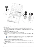
3. Install the replacement PCIe card in the riser by aligning the card with the socket, press the card into the
socket and then close the side panel on the riser, if present.
Be sure that you properly align the card in the slot and exert even pressure on the card when seating it in
the socket. The PCIe card must be fully and evenly seated in the slot.
If you are installing a card in the bottom slot and cannot see the card socket well, remove
the top card so that you can see the card socket, install the card, and then reinstall the card
you removed from the top slot.
4. Reinstall the riser:
a. Align the riser with the pins to the side of the riser socket, lower the riser down on the pins.
b. Push the riser squarely into the socket on the motherboard.
c. Rotate the latch down flush with the sheet metal on the riser.
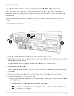
Step 4: Replace the mezzanine card
The mezzanine card is located under riser number 3 (slots 4 and 5). You must remove
that riser to access the mezzanine card, replace the mezzanine card, and then reinstall
riser number 3. See the FRU map on the controller module for more information.
You can use the following animation, illustration, or the written steps to replace the mezzanine card.
574
Summary of Contents for AFF A700
Page 4: ...AFF and FAS System Documentation 1...
Page 208: ...3 Close the controller module cover and tighten the thumbscrew 205...
Page 248: ...2 Close the controller module cover and tighten the thumbscrew 245...
Page 308: ...Power supply Cam handle release latch Power and Fault LEDs Cam handle 305...
Page 381: ...Power supply Cam handle release latch Power and Fault LEDs Cam handle 378...
Page 437: ...1 Locate the DIMMs on your controller module 434...
Page 605: ...602...
Page 1117: ...3 Close the controller module cover and tighten the thumbscrew 1114...
Page 1157: ...2 Close the controller module cover and tighten the thumbscrew 1154...
Page 1228: ...Power supply Cam handle release latch Power and Fault LEDs Cam handle 1225...
Page 1300: ...Power supply Cam handle release latch Power and Fault LEDs Cam handle 1297...
Page 1462: ...Installing SuperRail to round hole four post rack 1459...
Page 1602: ...1599...
Page 1630: ...1627...
Page 1634: ...Orange ring on horizontal bracket Cable chain 1631...
Page 1645: ...Guide rail 1642...
Page 1669: ...Attention LED light on 1666...