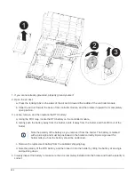

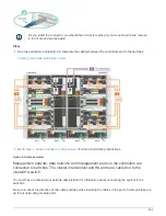

2. Identify the power supply you want to replace, based on console error messages or through the LEDs on
the power supplies.
3. Disconnect the power supply:
a. Open the power cable retainer, and then unplug the power cable from the power supply.
b. Unplug the power cable from the power source.
4. Remove the power supply:
a. Rotate the cam handle so that it can be used to pull the power supply out of the chassis.
b. Press the blue locking tab to release the power supply from the chassis.
c. Using both hands, pull the power supply out of the chassis, and then set it aside.
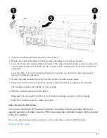
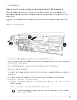
5. Using both hands, support and align the edges of the power supply with the opening in the controller
module, and then gently push the power supply into the controller module until the locking tab clicks into
place.
The power supplies will only properly engage with the internal connector and lock in place one way.
To avoid damaging the internal connector, do not use excessive force when sliding the
power supply into the system.
6. Rotate the cam handle so that it is flush against the power supply.
7. Reconnect the power supply cabling:
a. Reconnect the power cable to the power supply and the power source.
b. Secure the power cable to the power supply using the power cable retainer.
Once power is restored to the power supply, the status LED should be green.
8. After you replace the part, you can return the failed part to NetApp, as described in the RMA instructions
shipped with the kit. Contact technical support at
, 888-463-8277 (North America), 00-800-
44-638277 (Europe), or +800-800-80-800 (Asia/Pacific) if you need the RMA number or additional help
with the replacement procedure.
Replace the real-time clock battery - AFF A400
You replace the real-time clock (RTC) battery in the controller module so that your
system’s services and applications that depend on accurate time synchronization
continue to function.
• You can use this procedure with all versions of ONTAP supported by your system
• All other components in the system must be functioning properly; if not, you must contact technical support.
Step 1: Shut down the impaired controller
You can shut down or take over the impaired controller using different procedures,
depending on the storage system hardware configuration.
Option 1: Most configurations
To shut down the impaired node, you must determine the status of the node and, if
580
Summary of Contents for AFF A700
Page 4: ...AFF and FAS System Documentation 1...
Page 208: ...3 Close the controller module cover and tighten the thumbscrew 205...
Page 248: ...2 Close the controller module cover and tighten the thumbscrew 245...
Page 308: ...Power supply Cam handle release latch Power and Fault LEDs Cam handle 305...
Page 381: ...Power supply Cam handle release latch Power and Fault LEDs Cam handle 378...
Page 437: ...1 Locate the DIMMs on your controller module 434...
Page 605: ...602...
Page 1117: ...3 Close the controller module cover and tighten the thumbscrew 1114...
Page 1157: ...2 Close the controller module cover and tighten the thumbscrew 1154...
Page 1228: ...Power supply Cam handle release latch Power and Fault LEDs Cam handle 1225...
Page 1300: ...Power supply Cam handle release latch Power and Fault LEDs Cam handle 1297...
Page 1462: ...Installing SuperRail to round hole four post rack 1459...
Page 1602: ...1599...
Page 1630: ...1627...
Page 1634: ...Orange ring on horizontal bracket Cable chain 1631...
Page 1645: ...Guide rail 1642...
Page 1669: ...Attention LED light on 1666...