


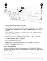
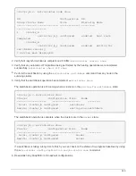
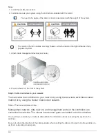
As you insert the connector, you should feel it click into place; if you do not feel it click, remove
it, turn it around and try again.
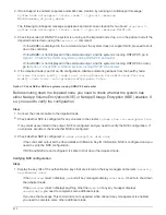
Steps
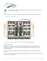
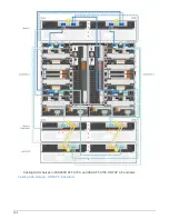
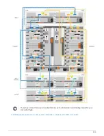
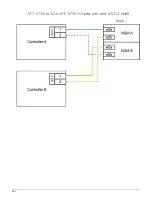
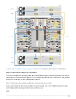
1. Use the animation or illustration to complete the cabling between the controllers and to the switches:
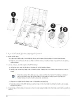
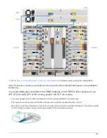
1. Go to
Step 4: Cable controllers to drive shelves
for drive shelf cabling instructions.
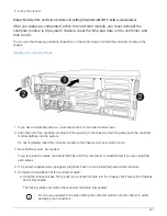
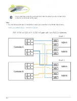
Step 4: Cable controllers to drive shelves
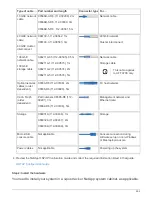
You can cable your new system to DS212C, DS224C, or NS224 shelves, depending on if
it is an AFF or FAS system.
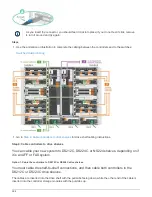
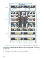
Option 1: Cable the controllers to DS212C or DS224C drive shelves
You must cable the shelf-to-shelf connections, and then cable both controllers to the
DS212C or DS224C drive shelves.
The cables are inserted into the drive shelf with the pull-tabs facing down, while the other end of the cable is
inserted into the controller storage modules with the pull-tabs up.
596
Summary of Contents for AFF A700
Page 4: ...AFF and FAS System Documentation 1...
Page 208: ...3 Close the controller module cover and tighten the thumbscrew 205...
Page 248: ...2 Close the controller module cover and tighten the thumbscrew 245...
Page 308: ...Power supply Cam handle release latch Power and Fault LEDs Cam handle 305...
Page 381: ...Power supply Cam handle release latch Power and Fault LEDs Cam handle 378...
Page 437: ...1 Locate the DIMMs on your controller module 434...
Page 605: ...602...
Page 1117: ...3 Close the controller module cover and tighten the thumbscrew 1114...
Page 1157: ...2 Close the controller module cover and tighten the thumbscrew 1154...
Page 1228: ...Power supply Cam handle release latch Power and Fault LEDs Cam handle 1225...
Page 1300: ...Power supply Cam handle release latch Power and Fault LEDs Cam handle 1297...
Page 1462: ...Installing SuperRail to round hole four post rack 1459...
Page 1602: ...1599...
Page 1630: ...1627...
Page 1634: ...Orange ring on horizontal bracket Cable chain 1631...
Page 1645: ...Guide rail 1642...
Page 1669: ...Attention LED light on 1666...


