


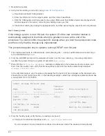
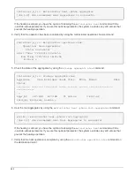
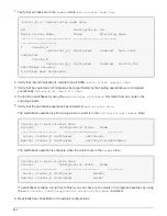

cluster_B::> metrocluster show
Cluster Configuration State Mode
-------------------- ------------------- ---------
Local: cluster_B configured switchover
Remote: cluster_A configured waiting-for-switchback
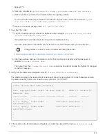
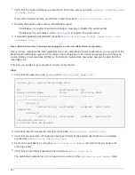
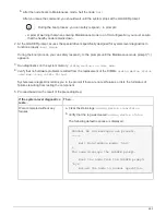
The switchback operation is complete when the clusters are in the
normal
state.:
cluster_B::> metrocluster show
Cluster Configuration State Mode
-------------------- ------------------- ---------
Local: cluster_B configured normal
Remote: cluster_A configured normal
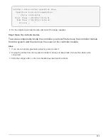
If a switchback is taking a long time to finish, you can check on the status of in-progress baselines by using
the
metrocluster config-replication resync-status show
command.
6. Reestablish any SnapMirror or SnapVault configurations.
Return the failed part to NetApp
After you replace the part, you can return the failed part to NetApp, as described in the RMA instructions
shipped with the kit. Contact technical support at
, 888-463-8277 (North America), 00-800-44-
638277 (Europe), or +800-800-80-800 (Asia/Pacific) if you need the RMA number or additional help with the
replacement procedure.
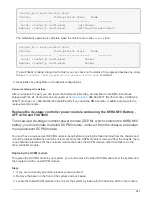
Replace the de-stage controller power module containing the NVRAM10 Battery -
AFF A700 and FAS9000
To hot-swap a de-stage controller power module (DCPM), which contains the NVRAM10
battery, you must locate the failed DCPM module, remove it from the chassis, and install
the replacement DCPM module.
You must have a replacement DCPM module in-hand before removing the failed module from the chassis and
it must be replaced within five minutes of removal. Once the DCPM module is removed from the chassis, there
is no shutdown protection for the controller module that owns the DCPM module, other than failover to the
other controller module.
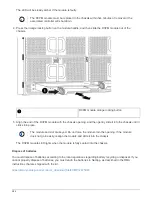
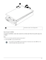
Replacing the DCPM module
To replace the DCPM module in your system, you must remove the failed DCPM module from the system and
then replace it with a new DCPM module.
Steps
1. If you are not already grounded, properly ground yourself.
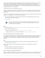
2. Remove the bezel on the front of the system and set it aside.
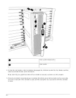
3. Locate the failed DCPM module in the front of the system by looking for the Attention LED on the module.
683
Summary of Contents for AFF A700
Page 4: ...AFF and FAS System Documentation 1...
Page 208: ...3 Close the controller module cover and tighten the thumbscrew 205...
Page 248: ...2 Close the controller module cover and tighten the thumbscrew 245...
Page 308: ...Power supply Cam handle release latch Power and Fault LEDs Cam handle 305...
Page 381: ...Power supply Cam handle release latch Power and Fault LEDs Cam handle 378...
Page 437: ...1 Locate the DIMMs on your controller module 434...
Page 605: ...602...
Page 1117: ...3 Close the controller module cover and tighten the thumbscrew 1114...
Page 1157: ...2 Close the controller module cover and tighten the thumbscrew 1154...
Page 1228: ...Power supply Cam handle release latch Power and Fault LEDs Cam handle 1225...
Page 1300: ...Power supply Cam handle release latch Power and Fault LEDs Cam handle 1297...
Page 1462: ...Installing SuperRail to round hole four post rack 1459...
Page 1602: ...1599...
Page 1630: ...1627...
Page 1634: ...Orange ring on horizontal bracket Cable chain 1631...
Page 1645: ...Guide rail 1642...
Page 1669: ...Attention LED light on 1666...


