
b. After the node boots to Maintenance mode, halt the node:
halt
After you issue the command, you should wait until the system stops at the LOADER prompt.
During the boot process, you can safely respond
y
to prompts:
▪
A prompt warning that when entering Maintenance mode in an HA configuration, you must ensure
that the healthy node remains down.
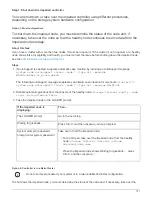
2. At the LOADER prompt, access the special drivers specifically designed for system-level diagnostics to
function properly:
boot_diags
During the boot process, you can safely respond
y
to the prompts until the Maintenance mode prompt (*>)
appears.
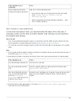
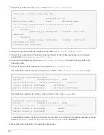
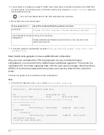
3. Run diagnostics on the system memory:
sldiag device run -dev mem
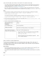
4. Verify that no hardware problems resulted from the replacement of the DIMMs:
sldiag device status
-dev mem -long -state failed
System-level diagnostics returns you to the prompt if there are no test failures, or lists the full status of
failures resulting from testing the component.
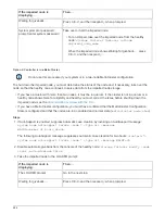
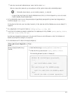
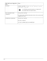
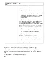
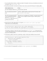
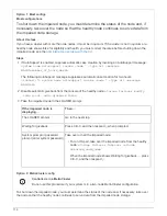
5. Proceed based on the result of the preceding step:
If the system-level diagnostics
tests…
Then…
Were completed without any
failures
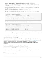
a. Clear the status logs:
sldiag device clearstatus
b. Verify that the log was cleared:
sldiag device status
The following default response is displayed:
SLDIAG: No log messages are present.
-----
.. Exit Maintenance mode: `halt`
+
The node displays the LOADER prompt.
.. Boot the node from the LOADER prompt:
`bye`
.. Return the node to normal operation.
695
Summary of Contents for AFF A700
Page 4: ...AFF and FAS System Documentation 1...
Page 208: ...3 Close the controller module cover and tighten the thumbscrew 205...
Page 248: ...2 Close the controller module cover and tighten the thumbscrew 245...
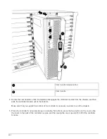
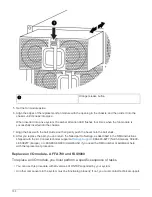
Page 308: ...Power supply Cam handle release latch Power and Fault LEDs Cam handle 305...
Page 381: ...Power supply Cam handle release latch Power and Fault LEDs Cam handle 378...
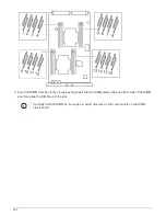
Page 437: ...1 Locate the DIMMs on your controller module 434...
Page 605: ...602...
Page 1117: ...3 Close the controller module cover and tighten the thumbscrew 1114...
Page 1157: ...2 Close the controller module cover and tighten the thumbscrew 1154...
Page 1228: ...Power supply Cam handle release latch Power and Fault LEDs Cam handle 1225...
Page 1300: ...Power supply Cam handle release latch Power and Fault LEDs Cam handle 1297...
Page 1462: ...Installing SuperRail to round hole four post rack 1459...
Page 1602: ...1599...
Page 1630: ...1627...
Page 1634: ...Orange ring on horizontal bracket Cable chain 1631...
Page 1645: ...Guide rail 1642...
Page 1669: ...Attention LED light on 1666...


