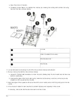


9. When prompted, either enter the name of the image or accept the default image displayed inside the
brackets on your screen.
10. After the image is installed, start the restoration process:
a. Record the IP address of the impaired node that is displayed on the screen.
b. Press
y
when prompted to restore the backup configuration.
c. Press
y
when prompted to confirm that the backup procedure was successful.
11. From the partner node in advanced privilege level, start the configuration synchronization using the IP
address recorded in the previous step:
system node restore-backup -node local -target
-address
impaired_node_IP_address
12. After the configuration synchronization is complete without errors, press
y
when prompted to confirm that
the backup procedure was successful.
13. Press
y
when prompted whether to use the restored copy, and then press
y
when prompted to reboot the
node.
14. Exit advanced privilege level on the healthy node.
Option 2: Transfer the boot image to the boot media using a USB flash drive
This procedure should only be used if the secondary boot media restore failed or if the
image.tgz file is not found on the secondary boot media.
• You must have a USB flash drive, formatted to FAT32, with at least 4GB capacity.
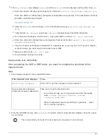
• A copy of the same image version of ONTAP as what the impaired controller was running. You can
download the appropriate image from the Downloads section on the NetApp Support Site
◦
If NVE is enabled, download the image with NetApp Volume Encryption, as indicated in the download
button.
◦
If NVE is not enabled, download the image without NetApp Volume Encryption, as indicated in the
download button.
• If your system is an HA pair, you must have a network connection.
• If your system is a stand-alone system you do not need a network connection, but you must perform an
additional reboot when restoring the var file system.
Steps
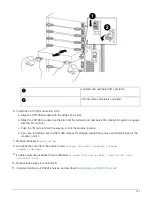
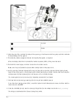
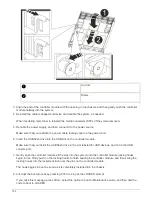
1. If you are not already grounded, properly ground yourself.
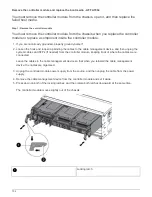
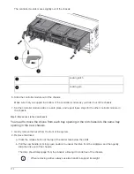
2. If you have not already done so, close the air duct:
a. Swing the air duct all the way down to the controller module.
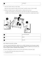
b. Slide the air duct toward the risers until the locking tabs click into place.
c. Inspect the air duct to make sure that it is properly seated and locked into place.
757
Summary of Contents for AFF A700
Page 4: ...AFF and FAS System Documentation 1...
Page 208: ...3 Close the controller module cover and tighten the thumbscrew 205...
Page 248: ...2 Close the controller module cover and tighten the thumbscrew 245...
Page 308: ...Power supply Cam handle release latch Power and Fault LEDs Cam handle 305...
Page 381: ...Power supply Cam handle release latch Power and Fault LEDs Cam handle 378...
Page 437: ...1 Locate the DIMMs on your controller module 434...
Page 605: ...602...
Page 1117: ...3 Close the controller module cover and tighten the thumbscrew 1114...
Page 1157: ...2 Close the controller module cover and tighten the thumbscrew 1154...
Page 1228: ...Power supply Cam handle release latch Power and Fault LEDs Cam handle 1225...
Page 1300: ...Power supply Cam handle release latch Power and Fault LEDs Cam handle 1297...
Page 1462: ...Installing SuperRail to round hole four post rack 1459...
Page 1602: ...1599...
Page 1630: ...1627...
Page 1634: ...Orange ring on horizontal bracket Cable chain 1631...
Page 1645: ...Guide rail 1642...
Page 1669: ...Attention LED light on 1666...