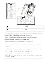
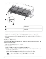

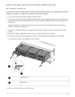
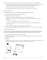
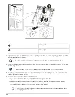

5. Complete the reinstallation of the controller module:
a. If you have not already done so, reinstall the cable management device.
b. Firmly push the controller module into the chassis until it meets the midplane and is fully seated.
The locking latches rise when the controller module is fully seated.
Do not use excessive force when sliding the controller module into the chassis to avoid
damaging the connectors.
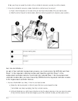
The controller module begins to boot as soon as it is fully seated in the chassis. Be prepared to
interrupt the boot process.
c. Rotate the locking latches upward, tilting them so that they clear the locking pins, and then lower them
into the locked position.
d. Interrupt the boot process by pressing
Ctrl-C
when you see
Press Ctrl-C for Boot Menu
.
e. Select the option to boot to Maintenance mode from the displayed menu.
6. Repeat the preceding steps to install the second controller into the new chassis.
Complete the restoration and replacement process - AFF A700s
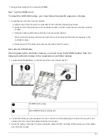
Step 1: Verify and set the HA state of the chassis
You must verify the HA state of the chassis, and, if necessary, update the state to match
your system configuration.
1. In Maintenance mode, from either controller module, display the HA state of the local controller module and
chassis:
ha-config show
The HA state should be the same for all components.
2. If the displayed system state for the chassis does not match your system configuration:
a. Set the HA state for the chassis:
ha-config modify chassis
HA-state
The value for HA-state can be one of the following:
▪
ha
▪
non-ha
b. Confirm that the setting has changed:
ha-config show
3. If you have not already done so, recable the rest of your system.
4. Reinstall the bezel on the front of the system.
Step 2: Run diagnostics
After you have replaced a component in your system, you should run diagnostic tests on
that component.
Your system must be at the LOADER prompt to start diagnostics.
772
Summary of Contents for AFF A700
Page 4: ...AFF and FAS System Documentation 1...
Page 208: ...3 Close the controller module cover and tighten the thumbscrew 205...
Page 248: ...2 Close the controller module cover and tighten the thumbscrew 245...
Page 308: ...Power supply Cam handle release latch Power and Fault LEDs Cam handle 305...
Page 381: ...Power supply Cam handle release latch Power and Fault LEDs Cam handle 378...
Page 437: ...1 Locate the DIMMs on your controller module 434...
Page 605: ...602...
Page 1117: ...3 Close the controller module cover and tighten the thumbscrew 1114...
Page 1157: ...2 Close the controller module cover and tighten the thumbscrew 1154...
Page 1228: ...Power supply Cam handle release latch Power and Fault LEDs Cam handle 1225...
Page 1300: ...Power supply Cam handle release latch Power and Fault LEDs Cam handle 1297...
Page 1462: ...Installing SuperRail to round hole four post rack 1459...
Page 1602: ...1599...
Page 1630: ...1627...
Page 1634: ...Orange ring on horizontal bracket Cable chain 1631...
Page 1645: ...Guide rail 1642...
Page 1669: ...Attention LED light on 1666...