
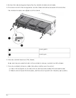
7. Repeat these steps for the remaining DIMMs.
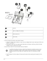
Step 7: Install the NVRAM module
To install the NVRAM module, you must follow the specific sequence of steps.
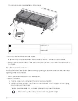
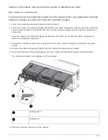
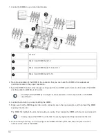
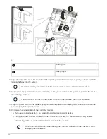
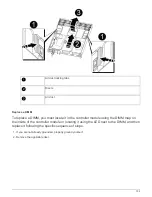
1. Install the riser into the controller module:
a. Align the lip of the riser with the underside of the controller module sheet metal.
b. Guide the riser along the pins in the controller module, and then lower the riser into the controller
module.
c. Swing the locking latch down and click it into the locked position.
When locked, the locking latch is flush with the top of the riser and the riser sits squarely in the
controller module.
d. Reinsert any SFP modules that were removed from the PCIe cards.
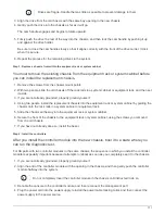
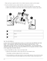
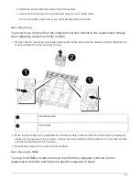
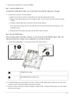
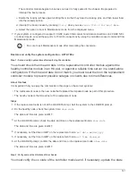
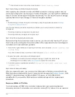
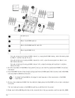
Step 8: Move the NVRAM battery
When replacing the controller module, you must move the NVRAM battery from the
impaired controller module to the replacement controller module
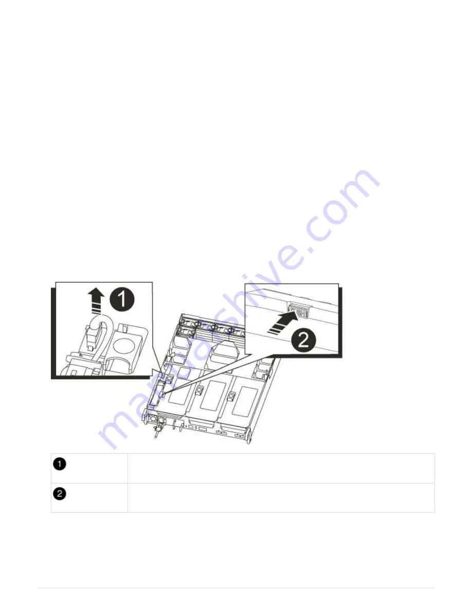
1. Locate the NVRAM battery on the left side of the riser module, Riser 1.
NVRAM battery plug
Blue NVRAM battery locking tab
2. Locate the battery plug and squeeze the clip on the face of the battery plug to release the plug from the
socket, and then unplug the battery cable from the socket.
3. Grasp the battery and press the blue locking tab marked PUSH, and then lift the battery out of the holder
and controller module.
783
Summary of Contents for AFF A700
Page 4: ...AFF and FAS System Documentation 1...
Page 208: ...3 Close the controller module cover and tighten the thumbscrew 205...
Page 248: ...2 Close the controller module cover and tighten the thumbscrew 245...
Page 308: ...Power supply Cam handle release latch Power and Fault LEDs Cam handle 305...
Page 381: ...Power supply Cam handle release latch Power and Fault LEDs Cam handle 378...
Page 437: ...1 Locate the DIMMs on your controller module 434...
Page 605: ...602...
Page 1117: ...3 Close the controller module cover and tighten the thumbscrew 1114...
Page 1157: ...2 Close the controller module cover and tighten the thumbscrew 1154...
Page 1228: ...Power supply Cam handle release latch Power and Fault LEDs Cam handle 1225...
Page 1300: ...Power supply Cam handle release latch Power and Fault LEDs Cam handle 1297...
Page 1462: ...Installing SuperRail to round hole four post rack 1459...
Page 1602: ...1599...
Page 1630: ...1627...
Page 1634: ...Orange ring on horizontal bracket Cable chain 1631...
Page 1645: ...Guide rail 1642...
Page 1669: ...Attention LED light on 1666...


