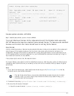
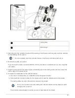
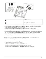

d. Interrupt the boot process by pressing
Ctrl-C
when you see
Press Ctrl-C for Boot Menu
.
e. Select the option to boot to Maintenance mode from the displayed menu.
Run diagnostics
After you have replaced a component in your system, you should run diagnostic tests on
that component.
Your system must be at the LOADER prompt to start diagnostics.
All commands in the diagnostic procedures are issued from the node where the component is being replaced.
Steps
1. If the node to be serviced is not at the LOADER prompt, reboot the node:
system node halt -node
node_name
After you issue the command, you should wait until the system stops at the LOADER prompt.
2. At the LOADER prompt, access the special drivers specifically designed for system-level diagnostics to
function properly:
boot_diags
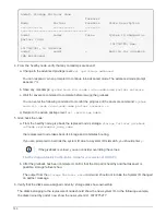
3. Select
Scan System
from the displayed menu to enable running the diagnostics tests.
4. Select
Test Memory
from the displayed menu.
5. Proceed based on the result of the preceding step:
◦
If the test failed, correct the failure, and then rerun the test.
◦
If the test reported no failures, select Reboot from the menu to reboot the system.
Return the failed part to NetApp
After you replace the part, you can return the failed part to NetApp, as described in the
RMA instructions shipped with the kit. Contact technical support at
, 888-
463-8277 (North America), 00-800-44-638277 (Europe), or +800-800-80-800
(Asia/Pacific) if you need the RMA number or additional help with the replacement
procedure.
Fan
Shut down the impaired node - AFF A700s
To shut down the impaired node, you must determine the status of the node and, if
necessary, take over the node so that the healthy node continues to serve data from the
impaired node storage.
About this task
If you have a cluster with more than two nodes, it must be in quorum. If the cluster is not in quorum or a healthy
node shows false for eligibility and health, you must correct the issue before shutting down the impaired node;
see the
Administration overview with the CLI
.
Steps
798
Summary of Contents for AFF A700
Page 4: ...AFF and FAS System Documentation 1...
Page 208: ...3 Close the controller module cover and tighten the thumbscrew 205...
Page 248: ...2 Close the controller module cover and tighten the thumbscrew 245...
Page 308: ...Power supply Cam handle release latch Power and Fault LEDs Cam handle 305...
Page 381: ...Power supply Cam handle release latch Power and Fault LEDs Cam handle 378...
Page 437: ...1 Locate the DIMMs on your controller module 434...
Page 605: ...602...
Page 1117: ...3 Close the controller module cover and tighten the thumbscrew 1114...
Page 1157: ...2 Close the controller module cover and tighten the thumbscrew 1154...
Page 1228: ...Power supply Cam handle release latch Power and Fault LEDs Cam handle 1225...
Page 1300: ...Power supply Cam handle release latch Power and Fault LEDs Cam handle 1297...
Page 1462: ...Installing SuperRail to round hole four post rack 1459...
Page 1602: ...1599...
Page 1630: ...1627...
Page 1634: ...Orange ring on horizontal bracket Cable chain 1631...
Page 1645: ...Guide rail 1642...
Page 1669: ...Attention LED light on 1666...