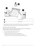
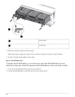
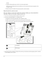

c. Rotate the locking latches upward, tilting them so that they clear the locking pins, and then lower them
into the locked position.
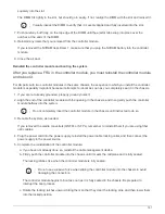
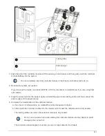
7. If your system is configured to support 10 GbE cluster interconnect and data connections on 40 GbE NICs
or onboard ports, convert these ports to 10 GbE connections by using the nicadmin convert command from
Maintenance mode.
Be sure to exit Maintenance mode after completing the conversion.
8. Return the node to normal operation by giving back its storage:
storage failover giveback
-ofnode
impaired_node_name
9. If automatic giveback was disabled, reenable it:
storage failover modify -node local -auto
-giveback true
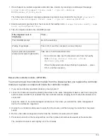
Return the failed part to NetApp
After you replace the part, you can return the failed part to NetApp, as described in the
RMA instructions shipped with the kit. Contact technical support at
, 888-
463-8277 (North America), 00-800-44-638277 (Europe), or +800-800-80-800
(Asia/Pacific) if you need the RMA number or additional help with the replacement
procedure.
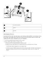
Replace the NVRAM module and/or NVRAM DIMMs - AFF A700s
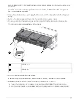
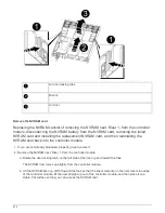
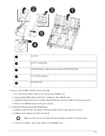
To replace a failed NVRAM card, you must remove the NVRAM riser, Riser 1, from the
controller module, remove the failed card from the riser, install the new NVRAM card in
the riser, and then reinstall the riser in the controller module. Because the system ID is
derived from the NVRAM card, if replacing the module, disks belonging to the system are
reassigned to the new system ID.
Before you begin
• All disk shelves must be working properly.
• If your system is in an HA pair, the partner node must be able to take over the node associated with the
NVRAM module that is being replaced.
• This procedure uses the following terminology:
◦
The
impaired
node is the node on which you are performing maintenance.
◦
The
healthy
node is the HA partner of the impaired node.
• This procedure includes steps for automatically or manually reassigning disks to the controller module
associated with the new NVRAM module. You must reassign the disks when directed to in the procedure.
Completing the disk reassignment before giveback can cause issues.
• You must replace the failed component with a replacement FRU component you received from your
provider.
• You cannot change any disks or disk shelves as part of this procedure.
Shut down the impaired node
Steps
809
Summary of Contents for AFF A700
Page 4: ...AFF and FAS System Documentation 1...
Page 208: ...3 Close the controller module cover and tighten the thumbscrew 205...
Page 248: ...2 Close the controller module cover and tighten the thumbscrew 245...
Page 308: ...Power supply Cam handle release latch Power and Fault LEDs Cam handle 305...
Page 381: ...Power supply Cam handle release latch Power and Fault LEDs Cam handle 378...
Page 437: ...1 Locate the DIMMs on your controller module 434...
Page 605: ...602...
Page 1117: ...3 Close the controller module cover and tighten the thumbscrew 1114...
Page 1157: ...2 Close the controller module cover and tighten the thumbscrew 1154...
Page 1228: ...Power supply Cam handle release latch Power and Fault LEDs Cam handle 1225...
Page 1300: ...Power supply Cam handle release latch Power and Fault LEDs Cam handle 1297...
Page 1462: ...Installing SuperRail to round hole four post rack 1459...
Page 1602: ...1599...
Page 1630: ...1627...
Page 1634: ...Orange ring on horizontal bracket Cable chain 1631...
Page 1645: ...Guide rail 1642...
Page 1669: ...Attention LED light on 1666...