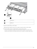
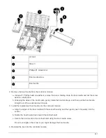

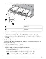
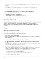
Air duct
Risers
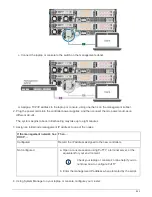
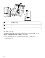
3. Align the end of the controller module with the opening in the chassis, and then gently push the controller
module halfway into the system.
4. Reinstall the cable management device and recable the system, as needed.
+
When recabling, remember to reinstall the media converters (SFPs or QSFPs) if they were removed.
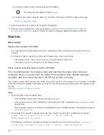
5. Plug the power cable into the power supply and reinstall the power cable retainer.
6. Insert the USB flash drive into the USB slot on the controller module.
+
Make sure that you install the USB flash drive in the slot labeled for USB devices, and not in the USB
console port.
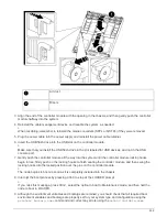
7. Gently push the controller module all the way into the system until the controller module locking hooks
begin to rise, firmly push on the locking hooks to finish seating the controller module, and then swing the
locking hooks into the locked position over the pins on the controller module.
+
The node begins to boot as soon as it is completely installed into the chassis.
8. Interrupt the boot process by pressing Ctrl-C to stop at the LOADER prompt.
+
If you miss this message, press Ctrl-C, select the option to boot to Maintenance mode, and then halt the
node to boot to LOADER.
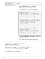
9. Although the environment variables and bootargs are retained, you should check that all required boot
environment variables and bootargs are properly set for your system type and configuration using the
printenv bootarg name
command and correct any errors using the
setenv variable-name
859
Summary of Contents for AFF A700
Page 4: ...AFF and FAS System Documentation 1...
Page 208: ...3 Close the controller module cover and tighten the thumbscrew 205...
Page 248: ...2 Close the controller module cover and tighten the thumbscrew 245...
Page 308: ...Power supply Cam handle release latch Power and Fault LEDs Cam handle 305...
Page 381: ...Power supply Cam handle release latch Power and Fault LEDs Cam handle 378...
Page 437: ...1 Locate the DIMMs on your controller module 434...
Page 605: ...602...
Page 1117: ...3 Close the controller module cover and tighten the thumbscrew 1114...
Page 1157: ...2 Close the controller module cover and tighten the thumbscrew 1154...
Page 1228: ...Power supply Cam handle release latch Power and Fault LEDs Cam handle 1225...
Page 1300: ...Power supply Cam handle release latch Power and Fault LEDs Cam handle 1297...
Page 1462: ...Installing SuperRail to round hole four post rack 1459...
Page 1602: ...1599...
Page 1630: ...1627...
Page 1634: ...Orange ring on horizontal bracket Cable chain 1631...
Page 1645: ...Guide rail 1642...
Page 1669: ...Attention LED light on 1666...


