

node_name
After you issue the command, you should wait until the system stops at the LOADER prompt.
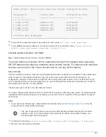
2. At the LOADER prompt, access the special drivers specifically designed for system-level diagnostics to
function properly:
boot_diags
3. Select
Scan System
from the displayed menu to enable running the diagnostics tests.
4. Select
Test Memory
from the displayed menu.
5. Proceed based on the result of the preceding step:
◦
If the test failed, correct the failure, and then rerun the test.
◦
If the test reported no failures, select Reboot from the menu to reboot the system.
During the boot process, you might see the following prompts:
▪
A prompt warning of a system ID mismatch and asking to override the system ID.
▪
A prompt warning that when entering Maintenance mode in an HA configuration you must ensure
that the healthy node remains down.
You can safely respond
y
to these prompts.
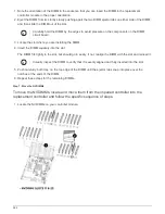
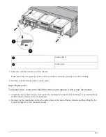
Recable the system and reassign disks - AFF A800
Continue the replacement procedure by recabling the storage and confirming disk
reassignment.
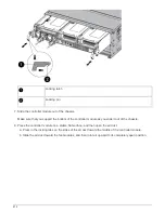
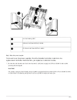
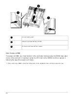
Step 1: Recable the system
After running diagnostics, you must recable the controller module’s storage and network
connections.
Steps
1. Recable the system.
2. Verify that the cabling is correct by using
.
a. Download and install Config Advisor.
b. Enter the information for the target system, and then click Collect Data.
c. Click the Cabling tab, and then examine the output. Make sure that all disk shelves are displayed and
all disks appear in the output, correcting any cabling issues you find.
d. Check other cabling by clicking the appropriate tab, and then examining the output from Config Advisor.
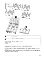
Step 2: Reassign disks
If the storage system is in an HA pair, the system ID of the new controller module is
automatically assigned to the disks when the giveback occurs at the end of the
procedure. You must confirm the system ID change when you boot the
replacement
node
and then verify that the change was implemented.
This procedure applies only to systems running ONTAP in an HA pair.
890
Summary of Contents for AFF A700
Page 4: ...AFF and FAS System Documentation 1...
Page 208: ...3 Close the controller module cover and tighten the thumbscrew 205...
Page 248: ...2 Close the controller module cover and tighten the thumbscrew 245...
Page 308: ...Power supply Cam handle release latch Power and Fault LEDs Cam handle 305...
Page 381: ...Power supply Cam handle release latch Power and Fault LEDs Cam handle 378...
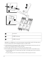
Page 437: ...1 Locate the DIMMs on your controller module 434...
Page 605: ...602...
Page 1117: ...3 Close the controller module cover and tighten the thumbscrew 1114...
Page 1157: ...2 Close the controller module cover and tighten the thumbscrew 1154...
Page 1228: ...Power supply Cam handle release latch Power and Fault LEDs Cam handle 1225...
Page 1300: ...Power supply Cam handle release latch Power and Fault LEDs Cam handle 1297...
Page 1462: ...Installing SuperRail to round hole four post rack 1459...
Page 1602: ...1599...
Page 1630: ...1627...
Page 1634: ...Orange ring on horizontal bracket Cable chain 1631...
Page 1645: ...Guide rail 1642...
Page 1669: ...Attention LED light on 1666...


