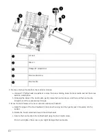
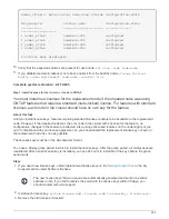
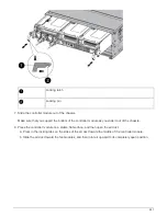
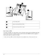
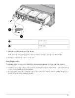
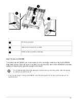
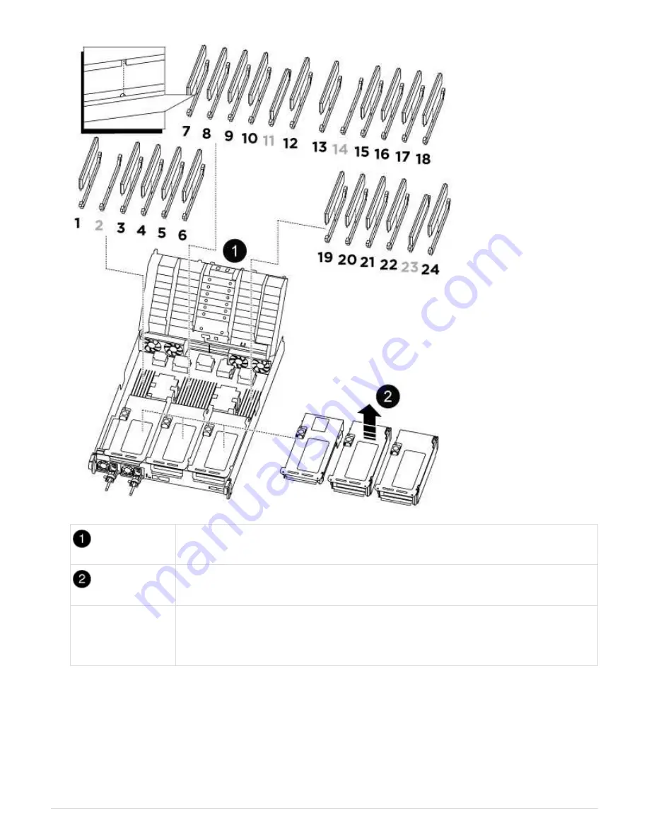
Air duct cover
Riser 1 and DIMM bank 1, and 3-6
Riser 2 and DIMM
bank 7-10, 12-13,
and 15-18
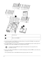
Riser 3 and DIMM 19 -22 and 24
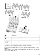
Note:
Slot 2 and 14 are left empty. Do not attempt to install DIMMs into these slots.
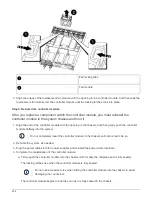
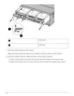
2. Note the orientation of the DIMM in the socket so that you can insert the replacement DIMM in the proper
orientation.
3. Eject the DIMM from its slot by slowly pushing apart the two DIMM ejector tabs on either side of the DIMM,
and then slide the DIMM out of the slot.
899
Summary of Contents for AFF A700
Page 4: ...AFF and FAS System Documentation 1...
Page 208: ...3 Close the controller module cover and tighten the thumbscrew 205...
Page 248: ...2 Close the controller module cover and tighten the thumbscrew 245...
Page 308: ...Power supply Cam handle release latch Power and Fault LEDs Cam handle 305...
Page 381: ...Power supply Cam handle release latch Power and Fault LEDs Cam handle 378...
Page 437: ...1 Locate the DIMMs on your controller module 434...
Page 605: ...602...
Page 1117: ...3 Close the controller module cover and tighten the thumbscrew 1114...
Page 1157: ...2 Close the controller module cover and tighten the thumbscrew 1154...
Page 1228: ...Power supply Cam handle release latch Power and Fault LEDs Cam handle 1225...
Page 1300: ...Power supply Cam handle release latch Power and Fault LEDs Cam handle 1297...
Page 1462: ...Installing SuperRail to round hole four post rack 1459...
Page 1602: ...1599...
Page 1630: ...1627...
Page 1634: ...Orange ring on horizontal bracket Cable chain 1631...
Page 1645: ...Guide rail 1642...
Page 1669: ...Attention LED light on 1666...


