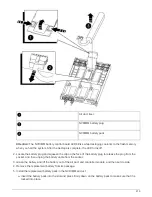
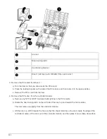
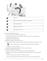
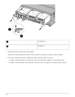
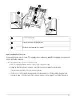
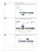

a. Firmly push the controller module into the chassis until it meets the midplane and is fully seated.
The locking latches rise when the controller module is fully seated.
Do not use excessive force when sliding the controller module into the chassis to avoid
damaging the connectors.
The controller module begins to boot as soon as it is fully seated in the chassis.
b. Rotate the locking latches upward, tilting them so that they clear the locking pins, and then lower them
into the locked position.
c. If you have not already done so, reinstall the cable management device.
6. Return the node to normal operation by giving back its storage:
storage failover giveback
-ofnode
impaired_node_name
7. If automatic giveback was disabled, reenable it:
storage failover modify -node local -auto
-giveback true
Step 5: Return the failed part to NetApp
After you replace the part, you can return the failed part to NetApp, as described in the
RMA instructions shipped with the kit. Contact technical support at
, 888-
463-8277 (North America), 00-800-44-638277 (Europe), or +800-800-80-800
(Asia/Pacific) if you need the RMA number or additional help with the replacement
procedure.
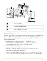
Replace a power supply - AFF A800
Replacing a power supply involves disconnecting the target power supply (PSU) from the
power source, unplugging the power cable, removing the old PSU and installing the
replacement PSU, and then reconnecting it to the power source.
• The power supplies are redundant and hot-swappable.
• This procedure is written for replacing one power supply at a time.
It is a best practice to replace the power supply within two minutes of removing it from the
chassis. The system continues to function, but ONTAP sends messages to the console
about the degraded power supply until the power supply is replaced.
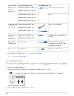
1. If you are not already grounded, properly ground yourself.
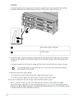
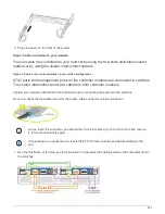
2. Identify the power supply you want to replace, based on console error messages or through the red
Fault LED on the power supply.
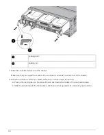
3. Disconnect the power supply:
a. Open the power cable retainer, and then unplug the power cable from the power supply.
b. Unplug the power cable from the power source.
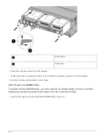
4. Rotate the cam handle such that it can be used to pull power supply out of the controller module while
pressing the locking tab.
929
Summary of Contents for AFF A700
Page 4: ...AFF and FAS System Documentation 1...
Page 208: ...3 Close the controller module cover and tighten the thumbscrew 205...
Page 248: ...2 Close the controller module cover and tighten the thumbscrew 245...
Page 308: ...Power supply Cam handle release latch Power and Fault LEDs Cam handle 305...
Page 381: ...Power supply Cam handle release latch Power and Fault LEDs Cam handle 378...
Page 437: ...1 Locate the DIMMs on your controller module 434...
Page 605: ...602...
Page 1117: ...3 Close the controller module cover and tighten the thumbscrew 1114...
Page 1157: ...2 Close the controller module cover and tighten the thumbscrew 1154...
Page 1228: ...Power supply Cam handle release latch Power and Fault LEDs Cam handle 1225...
Page 1300: ...Power supply Cam handle release latch Power and Fault LEDs Cam handle 1297...
Page 1462: ...Installing SuperRail to round hole four post rack 1459...
Page 1602: ...1599...
Page 1630: ...1627...
Page 1634: ...Orange ring on horizontal bracket Cable chain 1631...
Page 1645: ...Guide rail 1642...
Page 1669: ...Attention LED light on 1666...


