

6. Repeat the process for the remaining drives in the system.
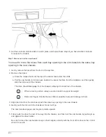
Step 4: Replace a chassis from within the equipment rack or system cabinet
You must remove the existing chassis from the equipment rack or system cabinet before
you can install the replacement chassis.
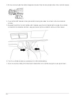
1. Remove the screws from the chassis mount points.
2. With the help of two or three people, slide the old chassis off the rack rails in a system cabinet or
L
brackets in an equipment rack, and then set it aside.
3. If you are not already grounded, properly ground yourself.
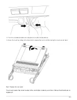
4. Using two or three people, install the replacement chassis into the equipment rack or system cabinet by
guiding the chassis onto the rack rails in a system cabinet or
L
brackets in an equipment rack.
5. Slide the chassis all the way into the equipment rack or system cabinet.
6. Secure the front of the chassis to the equipment rack or system cabinet, using the screws you removed
from the old chassis.
7. If you have not already done so, install the bezel.
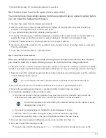
Step 5: Install the controller module
After you install the controller module and any other components into the new chassis,
you need to boot it to a state where you can run the interconnect diagnostic test.
For HA pairs with two controller modules in the same chassis, the sequence in which you install the controller
module is especially important because it attempts to reboot as soon as you completely seat it in the chassis.
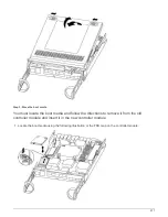
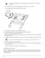
1. Align the end of the controller module with the opening in the chassis, and then gently push the controller
module halfway into the system.
Do not completely insert the controller module in the chassis until instructed to do so.
2. Recable the console to the controller module, and then reconnect the management port.
3. Repeat the preceding steps if there is a second controller to install in the new chassis.
4. Complete the installation of the controller module
a. With the cam handle in the open position, firmly push the controller module in until it meets the
midplane and is fully seated, and then close the cam handle to the locked position.
Do not use excessive force when sliding the controller module into the chassis to avoid
damaging the connectors.
b. If you have not already done so, reinstall the cable management device.
c. Bind the cables to the cable management device with the hook and loop strap.
d. Repeat the preceding steps for the second controller module in the new chassis.
5. Connect the power supplies to different power sources, and then turn them on.
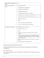
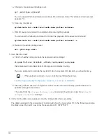
6. Boot each node to Maintenance mode:
a. As each node starts the booting, press
Ctrl-C
to interrupt the boot process when you see the
973
Summary of Contents for AFF A700
Page 4: ...AFF and FAS System Documentation 1...
Page 208: ...3 Close the controller module cover and tighten the thumbscrew 205...
Page 248: ...2 Close the controller module cover and tighten the thumbscrew 245...
Page 308: ...Power supply Cam handle release latch Power and Fault LEDs Cam handle 305...
Page 381: ...Power supply Cam handle release latch Power and Fault LEDs Cam handle 378...
Page 437: ...1 Locate the DIMMs on your controller module 434...
Page 605: ...602...
Page 1117: ...3 Close the controller module cover and tighten the thumbscrew 1114...
Page 1157: ...2 Close the controller module cover and tighten the thumbscrew 1154...
Page 1228: ...Power supply Cam handle release latch Power and Fault LEDs Cam handle 1225...
Page 1300: ...Power supply Cam handle release latch Power and Fault LEDs Cam handle 1297...
Page 1462: ...Installing SuperRail to round hole four post rack 1459...
Page 1602: ...1599...
Page 1630: ...1627...
Page 1634: ...Orange ring on horizontal bracket Cable chain 1631...
Page 1645: ...Guide rail 1642...
Page 1669: ...Attention LED light on 1666...