

see the
Administration overview with the CLI
.
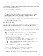
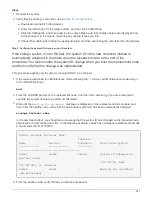
Steps
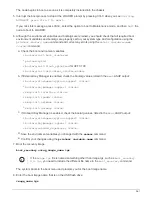
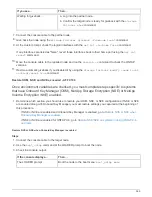
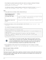
1. If AutoSupport is enabled, suppress automatic case creation by invoking an AutoSupport message:
system node autosupport invoke -node * -type all -message
MAINT=number_of_hours_downh
The following AutoSupport message suppresses automatic case creation for two hours:
cluster1:*>
system node autosupport invoke -node * -type all -message MAINT=2h
2. Disable automatic giveback from the console of the healthy node:
storage failover modify –node
local -auto-giveback false
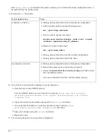
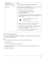
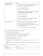
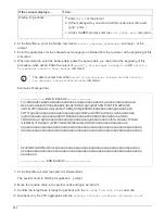
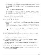
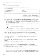
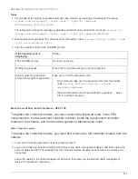
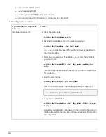
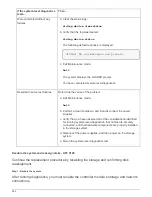
3. Take the impaired node to the LOADER prompt:
If the impaired node is
displaying…
Then…
The LOADER prompt
Go to the next step.
Waiting for giveback…
Press Ctrl-C, and then respond
y
when prompted.
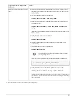
System prompt or password
prompt (enter system password)
Take over or halt the impaired node:
• For an HA pair, take over the impaired node from the healthy
node:
storage failover takeover -ofnode
impaired_node_name
When the impaired node shows Waiting for giveback…, press
Ctrl-C, and then respond
y
.
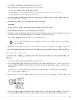
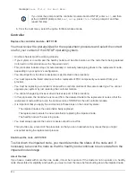
Move the controller module hardware - AFF C190
To replace the controller module, you must remove the impaired node, move FRU
components to the replacement controller module, install the replacement controller
module in the chassis, and then boot the system to Maintenance mode.
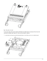
Step 1: Open the system
To replace the controller module, you must first remove the old controller module from the
chassis.
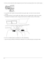
1. If you are not already grounded, properly ground yourself.
2. Loosen the hook and loop strap binding the cables to the cable management device, and then unplug the
system cables and SFPs (if needed) from the controller module, keeping track of where the cables were
connected.
Leave the cables in the cable management device so that when you reinstall the cable management
device, the cables are organized.
975
Summary of Contents for AFF A700
Page 4: ...AFF and FAS System Documentation 1...
Page 208: ...3 Close the controller module cover and tighten the thumbscrew 205...
Page 248: ...2 Close the controller module cover and tighten the thumbscrew 245...
Page 308: ...Power supply Cam handle release latch Power and Fault LEDs Cam handle 305...
Page 381: ...Power supply Cam handle release latch Power and Fault LEDs Cam handle 378...
Page 437: ...1 Locate the DIMMs on your controller module 434...
Page 605: ...602...
Page 1117: ...3 Close the controller module cover and tighten the thumbscrew 1114...
Page 1157: ...2 Close the controller module cover and tighten the thumbscrew 1154...
Page 1228: ...Power supply Cam handle release latch Power and Fault LEDs Cam handle 1225...
Page 1300: ...Power supply Cam handle release latch Power and Fault LEDs Cam handle 1297...
Page 1462: ...Installing SuperRail to round hole four post rack 1459...
Page 1602: ...1599...
Page 1630: ...1627...
Page 1634: ...Orange ring on horizontal bracket Cable chain 1631...
Page 1645: ...Guide rail 1642...
Page 1669: ...Attention LED light on 1666...