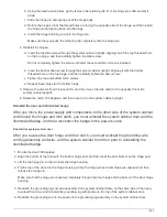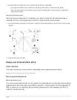
If the ID takes longer than 15 seconds to blink, press and hold the button again, making
sure to press it in all the way.
d. Press and release the button to advance the number until you reach the desired number from 0 to 9.
e. Repeat substeps 4c and 4d to set the second number of the shelf ID.
It can take up to three seconds (instead of 15 seconds) for the number to blink.
f. Press and hold the button until the second number stops blinking.
After about five seconds, both numbers start blinking and the amber LED on the ODP illuminates.
g. Power-cycle the shelf to make the shelf ID take effect.
You must unplug both power cords from the shelf, wait 10 seconds, and then plug them back in.
When power is restored to the power supplies, their bicolored LEDs illuminate green.
Cable a drive shelf for a hot-add
You cable each NS224 drive shelf you are hot-adding so that each shelf has two
connections to each controller module in the HA pair. Depending on the number of
shelves you are hot-adding and your platform model, you use RoCE capable ports on
board the controllers, on RoCE capable PCIe cards, a combination of both, or on RoCE
capable I/O modules.
Considerations when cabling for a hot-add
Familiarizing yourself with proper cable connector orientation, and the location and
labeling of ports on the NS224 NSM drive shelf modules can be helpful before cabling
your hot-added shelf.
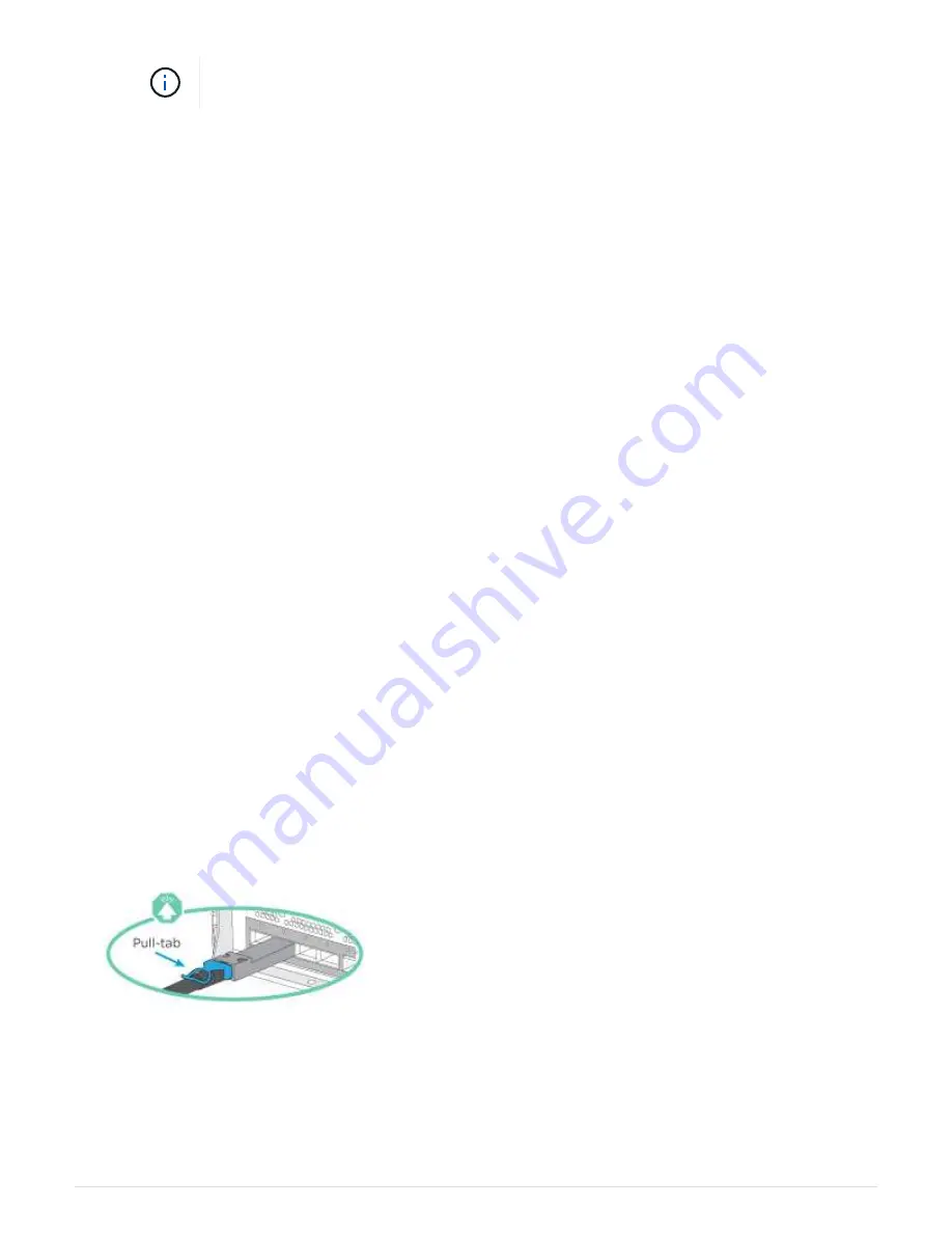
• Cables are inserted with the connector pull-tab facing up.
When a cable is inserted correctly, it clicks into place.
After you connect both ends of the cable, the shelf and controller port LNK (green) LEDs illuminate. If a
port LNK LED does not illuminate, reseat the cable.
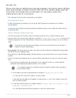
• You can use the following illustration to help you physically identify the shelf NSM ports, e0a and e0b:
1499
Summary of Contents for AFF A700
Page 4: ...AFF and FAS System Documentation 1...
Page 208: ...3 Close the controller module cover and tighten the thumbscrew 205...
Page 248: ...2 Close the controller module cover and tighten the thumbscrew 245...
Page 308: ...Power supply Cam handle release latch Power and Fault LEDs Cam handle 305...
Page 381: ...Power supply Cam handle release latch Power and Fault LEDs Cam handle 378...
Page 437: ...1 Locate the DIMMs on your controller module 434...
Page 605: ...602...
Page 1117: ...3 Close the controller module cover and tighten the thumbscrew 1114...
Page 1157: ...2 Close the controller module cover and tighten the thumbscrew 1154...
Page 1228: ...Power supply Cam handle release latch Power and Fault LEDs Cam handle 1225...
Page 1300: ...Power supply Cam handle release latch Power and Fault LEDs Cam handle 1297...
Page 1462: ...Installing SuperRail to round hole four post rack 1459...
Page 1602: ...1599...
Page 1630: ...1627...
Page 1634: ...Orange ring on horizontal bracket Cable chain 1631...
Page 1645: ...Guide rail 1642...
Page 1669: ...Attention LED light on 1666...

