background image

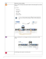
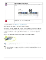
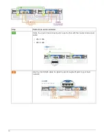
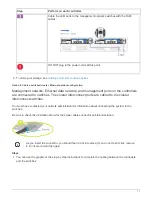
2. To cable your storage, see 

Cabling controllers to drive shelves

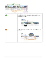
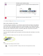
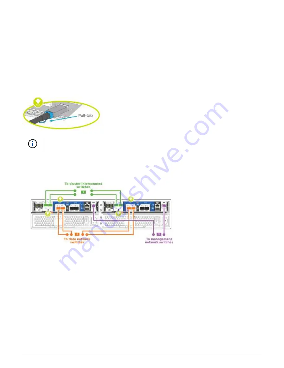
Option 2: Cable a switched cluster, unified network configuration

Management network, UTA2 data network, and management ports on the controllers are
connected to switches. The cluster interconnect ports are cabled to the cluster
interconnect switches.

You must have contacted your network administrator for information about connecting the system to the
switches.

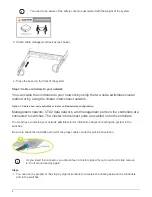
Be sure to check the illustration arrow for the proper cable connector pull-tab orientation.

As you insert the connector, you should feel it click into place; if you do not feel it click, remove
it, turn it around and try again.

Steps

1. You can use the graphic or the step-by step instructions to complete the cabling between the controllers

and the switches:

7

Summary of Contents for FAS2700 Series

Page 1: ...2700 systems ONTAP Systems NetApp April 04 2022 This PDF was generated from https docs netapp com us en ontap systems fas2700 install setup html on April 04 2022 Always check docs netapp com for the latest ...

Page 2: ...Table of Contents FAS2700 System Documentation 1 Install and setup 1 Maintain 18 ...

Page 3: ... system bring up Use this guide if you are familiar with installing NetApp systems Access the Installation and Setup Instructions PDF poster AFF A220 FAS2700 Systems Installation and Setup Instructions Videos AFF A220 and FAS2700 There are two videos one showing how to rack and cable your system and one showing an example of using the System Manager Guided Setup to perform initial system configura...

Page 4: ...m NetApp Hardware Universe Find the Release Notes for your version of ONTAP 9 You need to provide the following at your site Rack space for the storage system Phillips 2 screwdriver Additional networking cables to connect your system to your network switch and laptop or console with a Web browser A laptop or console with an RJ 45 connection and access to a Web browser Steps 1 Unpack the contents o...

Page 5: ...R6 112 00196 5m Management network and Ethernet data Storage order dependent Part number X66030A 112 00435 0 5m X66031A 112 00436 1m X66032A 112 00437 2m X66033A 112 00438 3m Storage Micro USB console cable Not applicable Console connection during software setup on non Windows or Mac laptop console Power cables Not applicable Powering up the system 6 Download and complete the Cluster configuration...

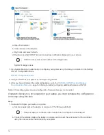
Page 6: ...nagement network UTA2 data network and management ports on the controllers are connected to switches The cluster interconnect ports are cabled on both controllers You must have contacted your network administrator for information about connecting the system to the switches Be sure to check the illustration arrow for the proper cable connector pull tab orientation As you insert the connector you sh...

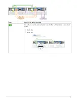
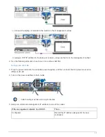
Page 7: ...Step Perform on each controller Cable the cluster interconnect ports to each other with the cluster interconnect cable e0a to e0a e0b to e0b 5 ...

Page 8: ... An FC host 0c and 0d or 0e and 0f A 10GbE e0c and e0d or e0e and e0f You can connect one port pair as CNA and one port pair as FC or you can connect both port pairs as CNA or both port pairs as FC Cable the e0M ports to the management network switches with the RJ45 cables DO NOT plug in the power cords at this point 6 ...

Page 9: ...r interconnect switches You must have contacted your network administrator for information about connecting the system to the switches Be sure to check the illustration arrow for the proper cable connector pull tab orientation As you insert the connector you should feel it click into place if you do not feel it click remove it turn it around and try again Steps 1 You can use the graphic or the ste...

Page 10: ...ter interconnect cable Use one of the following cable types to cable the UTA2 data ports to your host network An FC host 0c and 0d or 0e and 0f A 10GbE e0c and e0d or e0e and e0f You can connect one port pair as CNA and one port pair as FC or you can connect both port pairs as CNA or both port pairs as FC 8 ...

Page 11: ...e controllers are connected to switches The cluster interconnect ports are cabled on both controllers You must have contacted your network administrator for information about connecting the system to the switches Be sure to check the illustration arrow for the proper cable connector pull tab orientation As you insert the connector you should feel it click into place if you do not feel it click rem...

Page 12: ...m on each controller Cable the cluster interconnect ports to each other with the cluster interconnect cable e0a to e0a e0b to e0b Use the Cat 6 RJ45 cable to cable the e0c through e0f ports to your host network 10 ...

Page 13: ... connected to switches The cluster interconnect ports are cabled to the cluster interconnect switches You must have contacted your network administrator for information about connecting the system to the switches Be sure to check the illustration arrow for the proper cable connector pull tab orientation As you insert the connector you should feel it click into place if you do not feel it click rem...

Page 14: ...erform on each controller module Cable e0a and e0b to the cluster interconnect switches with the cluster interconnect cable Use the Cat 6 RJ45 cable to cable the e0c through e0f ports to your host network 12 ...

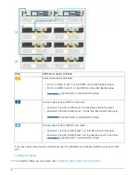
Page 15: ...ternal storage If you have a SAS tape drive you can use single path cabling If you have no external shelves MP HA cabling to internal drives is optional not shown if the SAS cables are ordered with the system Option 1 Cable storage on an HA pair with external drive shelves You must cable the shelf to shelf connections and then cable both controllers to the drive shelves Be sure to check the illust...

Page 16: ...ontroller 2 port 0a to IOM A port 1 on the first drive shelf in the stack mini SAS HD to mini SAS HD cables Connect each node to IOM B in the stack Controller 1 port 0a to IOM B port 1 on first drive shelf in the stack Controller 2 port 0b to IOM B port 3 on the last drive shelf in the stack mini SAS HD to mini SAS HD cables If you have more than one drive shelf stack see the Installation and Cabl...

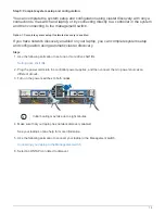
Page 17: ...figuration using automatic cluster discovery Steps 1 Use the following animation to set one or more drive shelf IDs Setting drive shelf IDs 2 Plug the power cords into the controller power supplies and then connect them to power sources on different circuits 3 Turn on the power switches to both nodes Initial booting may take up to eight minutes 4 Make sure that your laptop has network discovery en...

Page 18: ... configuration go to the ONTAP ONTAP System Manager Documentation Resources page for information about configuring additional features in ONTAP Option 2 Completing system setup and configuration if network discovery is not enabled If network discovery is not enabled on your laptop you must complete the configuration and setup using this task Steps 1 Cable and configure your laptop or console a Set...

Page 19: ...ve shelf IDs Setting drive shelf IDs 3 Plug the power cords into the controller power supplies and then connect them to power sources on different circuits 4 Turn on the power switches to both nodes Initial booting may take up to eight minutes 5 Assign an initial node management IP address to one of the nodes If the management network has DHCP Then Configured Record the IP address assigned to the ...

Page 20: ...uring additional features in ONTAP Maintain Boot media Overview of boot media replacement AFF A220 and FAS2700 The boot media stores a primary and secondary set of system boot image files that the system uses when it boots Depending on your network configuration you can perform either a nondisruptive or disruptive replacement You must have a USB flash drive formatted to FAT32 with the appropriate ...

Page 21: ...AutoSupport message system node autosupport invoke node type all message MAINT number_of_hours_downh The following AutoSupport message suppresses automatic case creation for two hours cluster1 system node autosupport invoke node type all message MAINT 2h 3 Check the version of ONTAP the system is running on the impaired controller if up or on the partner controller if the impaired controller is do...

Page 22: ...essage This command is not supported when onboard key management is enabled you need to complete some other additional steps 2 If the Restored column displayed anything other than yes or if any key manager displayed unavailable a Retrieve and restore all authentication keys and associated key IDs security key manager restore address If the command fails contact NetApp Support mysupport netapp com ...

Page 23: ...security key manager query If the Restored column displays yes and all key managers display available it s safe to shut down the impaired controller If the Restored column displays anything other than yes or if any key manager displays unavailable you need to complete some additional steps If you see the message This command is not supported when onboard key management is enabled you need to compl...

Page 24: ...needed in disaster scenarios where OKM might need to be manually recovered Copy the contents of the backup information to a separate file or your log You ll need it in disaster scenarios where you might need to manually recover OKM Return to admin mode set priv admin You can safely shut down the controller Option 2 Check NVE or NSE on systems running ONTAP 9 6 and later Before shutting down the im...

Page 25: ...n a Go to advanced privilege mode and enter y when prompted to continue set priv advanced b Enter the command to display the key management information security key manager onboard show backup c Copy the contents of the backup information to a separate file or your log file You ll need it in disaster scenarios where you might need to manually recover OKM d Return to admin mode set priv admin e Shu...

Page 26: ...xternal and the Restored column displays yes it s safe to shut down the impaired controller If the Key Manager type displays onboard and the Restored column displays yes you need to complete some additional steps If the Key Manager type displays external and the Restored column displays anything other than yes you need to complete some additional steps If the Key Manager type displays external and...

Page 27: ...ally back up the OKM information d Go to advanced privilege mode and enter y when prompted to continue set priv advanced e Enter the command to display the key management backup information security key manager onboard show backup f Copy the contents of the backup information to a separate file or your log file You ll need it in disaster scenarios where you might need to manually recover OKM g Ret...

Page 28: ... the controller so that the healthy controller continues to serve data from the impaired controller storage If you have a cluster with more than two nodes it must be in quorum If the cluster is not in quorum or a healthy controller shows false for eligibility and health you must correct the issue before shutting down the impaired controller see the Administration overview with the CLI If you have ...

Page 29: ...To access components inside the controller you must first remove the controller module from the system and then remove the cover on the controller module 1 If you are not already grounded properly ground yourself 2 Loosen the hook and loop strap binding the cables to the cable management device and then unplug the system cables and SFPs if needed from the controller module keeping track of where t...

Page 30: ...on a flat stable surface 6 Open the cover by sliding in the blue tabs to release the cover and then swing the cover up and open Step 2 Replace the boot media You must locate the boot media in the controller and follow the directions to replace it 28 ...

Page 31: ...completely in the socket If necessary remove the boot media and reseat it into the socket 6 Push the boot media down to engage the locking button on the boot media housing 7 Close the controller module cover Step 3 Transfer the boot image to the boot media You can install the system image to the replacement boot media using a USB flash drive with the image installed on it However you must restore ...

Page 32: ...humbscrew The controller begins to boot as soon as it is completely installed into the chassis 5 Interrupt the boot process to stop at the LOADER prompt by pressing Ctrl C when you see Starting AUTOBOOT press Ctrl C to abort If you miss this message press Ctrl C select the option to boot to Maintenance mode and then halt the controller to boot to LOADER 6 For systems with one controller in the cha...

Page 33: ... prompted to restore the backup configuration b Set the healthy controller to advanced privilege level set privilege advanced c Run the restore backup command system node restore backup node local target address impaired_node_IP_address d Return the controller to admin level set privilege admin e Press y when prompted to use the restored configuration f Press y when prompted to reboot the controll...

Page 34: ...g the net int revert command 10 Move the console cable to the repaired controller and run the version v command to check the ONTAP versions 11 Restore automatic giveback if you disabled it by using the storage failover modify node local auto giveback true command Restore OKM NSE and NVE as needed AFF A220 and FAS2700 Once environment variables are checked you must complete steps specific to system...

Page 35: ... enter y c At the LOADER prompt enter the boot_ontap menu command 4 At the Boot Menu enter the hidden command recover_onboard_keymanager and reply y at the prompt 5 Enter the passphrase for the onboard key manager you obtained from the customer at the beginning of this procedure 6 When prompted to enter the backup data paste the backup data you captured at the beginning of this procedure when aske...

Page 36: ...ver show command 10 Give back only the CFO aggregates with the storage failover giveback fromnode local only cfo aggregates true command If the command fails because of a failed disk physically disengage the failed disk but leave the disk in the slot until a replacement is received If the command fails because of an open CIFS session check with the customer on how to close out CIFS sessions Termin...

Page 37: ... back the target controller using the storage failover giveback fromnode local command 17 Check the giveback status 3 minutes after it reports complete using the storage failover show command If giveback is not complete after 20 minutes contact Customer Support 18 At the clustershell prompt enter the net int show is home false command to list the logical interfaces that are not on their home contr...

Page 38: ...o list the logical interfaces that are not on their home controller and port If any interfaces are listed as false revert those interfaces back to their home port using the net int revert command 7 Move the console cable to the target controller and run the version v command to check the ONTAP versions 8 Restore automatic giveback if you disabled it by using the storage failover modify node local ...

Page 39: ...1 Connect the console cable to the target controller 2 Use the boot_ontap command at the LOADER prompt to boot the controller 3 Check the console output If the console displays Then The login prompt Go to Step 7 Waiting for giveback a Log into the partner controller b Confirm the target controller is ready for giveback with the storage failover show command 4 Move the console cable to the partner ...

Page 40: ... the key IDs of the authentication keys If the command fails contact Customer Support If the Key Manager type onboard and the Restored column anything other than yes true use the security key manager onboard sync command to re sync the Key Manager type Use the security key manager key query to verify that the Restored column yes true for all authentication keys 11 Connect the console cable to the ...

Page 41: ... ONTAP 9 System Administration Reference You might want to erase the contents of your caching module before replacing it Steps 1 Although data on the caching module is encrypted you might want to erase any data from the impaired caching module and verify that the caching module has no data a Erase the data on the caching module system controller flash cache secure erase run b Verify that the data ...

Page 42: ...a cluster with more than two nodes it must be in quorum If the cluster is not in quorum or a healthy controller shows false for eligibility and health you must correct the issue before shutting down the impaired controller see the Administration overview with the CLI If you have a MetroCluster configuration you must have confirmed that the MetroCluster Configuration State is configured and that th...

Page 43: ... you are not already grounded properly ground yourself 2 Loosen the hook and loop strap binding the cables to the cable management device and then unplug the system cables and SFPs if needed from the controller module keeping track of where the cables were connected Leave the cables in the cable management device so that when you reinstall the cable management device the cables are organized 3 Rem...

Page 44: ...y sliding in the blue tabs to release the cover and then swing the cover up and open Step 3 Replace a caching module To replace a caching module referred to as the M 2 PCIe card on the label on your controller locate the slot inside the controller and follow the specific sequence of steps 42 ...

Page 45: ...y ground yourself 2 Locate the caching module at the rear of the controller module and remove it a Press the release tab b Remove the heatsink 3 Gently pull the caching module straight out of the housing 4 Align the edges of the caching module with the socket in the housing and then gently push it into the socket 5 Verify that the caching module is seated squarely and completely in the socket If n...

Page 46: ...eplace the cover on the controller module 3 Align the end of the controller module with the opening in the chassis and then gently push the controller module halfway into the system Do not completely insert the controller module in the chassis until instructed to do so 4 Recable the system as needed If you removed the media converters QSFPs or SFPs remember to reinstall them if you are using fiber...

Page 47: ... into the chassis to avoid damaging the connectors The controller begins to boot as soon as it is seated in the chassis b If you have not already done so reinstall the cable management device c Bind the cables to the cable management device with the hook and loop strap d When you see the message Press Ctrl C for Boot Menu press Ctrl C to interrupt the boot process If you miss the prompt and the co...

Page 48: ..._ontap press Ctrl C when prompted and then boot to Maintenance mode e From the boot menu select the option for Maintenance mode Step 5 Run system level diagnostics After installing a new caching module you should run diagnostics Your system must be at the LOADER prompt to start System Level Diagnostics All commands in the diagnostic procedures are issued from the controller where the component is ...

Page 49: ... a Clear the status logs sldiag device clearstatus b Verify that the log was cleared sldiag device status The following default response is displayed SLDIAG No log messages are present c Exit Maintenance mode halt The controller displays the LOADER prompt d Boot the controller from the LOADER prompt bye e Return the controller to normal operation If your controller is in an HA pair perform a give ...

Page 50: ...rompted to get to the Boot menu If you have two controller modules in the chassis fully seat the controller module you are servicing in the chassis The controller module boots up when fully seated If you have one controller module in the chassis connect the power supplies and then turn them on e Select Boot to maintenance mode from the menu f Exit Maintenance mode by entering the following command...

Page 51: ...surviving cluster 5 Verify that the switchback operation has completed metrocluster show The switchback operation is still running when a cluster is in the waiting for switchback state cluster_B metrocluster show Cluster Configuration State Mode Local cluster_B configured switchover Remote cluster_A configured waiting for switchback The switchback operation is complete when the clusters are in the...

Page 52: ...odules to the new chassis and that the chassis is a new component from NetApp This procedure is disruptive For a two controller cluster you will have a complete service outage and a partial outage in a multi node cluster Shut down the controllers AFF A220 and FAS2700 Shut down or take over the impaired controller using the appropriate procedure for your configuration Option 1 Most configurations Y...

Page 53: ...nding on your system if the NVMEM NVRAM LED is flashing there is content in the NVMEM NVRAM that has not been saved to disk You need to reboot the controller and start from the beginning of this procedure If repeated attempts to cleanly shut down the controller fail be aware that you might lose any data that was not saved to disk 3 Where applicable halt the second controller to avoid a possible qu...

Page 54: ...the impaired controller from the healthy controller storage failover takeover ofnode impaired_node_name When the impaired controller shows Waiting for giveback press Ctrl C and then respond y Move and replace hardware AFF A220 and FAS2700 Move the power supplies hard drives and controller module or modules from the impaired chassis to the new chassis and swap out the impaired chassis from the equi...

Page 55: ...r supply using the power cable locking mechanism Only connect the power cable to the power supply Do not connect the power cable to a power source at this time Step 2 Remove the controller module Remove the controller module or modules from the old chassis 1 Loosen the hook and loop strap binding the cables to the cable management device and then unplug the system cables and SFPs if needed from th...

Page 56: ...ssis The drive should disengage from the chassis allowing it to slide free of the chassis When removing a drive always use two hands to support its weight Drives are fragile Handle them as little as possible to prevent damage to them 3 Align the drive from the old chassis with the same bay opening in the new chassis 4 Gently push the drive into the chassis as far as it will go The cam handle engag...

Page 57: ...nect diagnostic test For HA pairs with two controller modules in the same chassis the sequence in which you install the controller module is especially important because it attempts to reboot as soon as you completely seat it in the chassis 1 Align the end of the controller module with the opening in the chassis and then gently push the controller module halfway into the system Do not completely i...

Page 58: ... miss the prompt and the controller modules boot to ONTAP enter halt and then at the LOADER prompt enter boot_ontap press Ctrl C when prompted and then repeat this step b From the boot menu select the option for Maintenance mode Restore and verify the configuration AFF A220 and FAS2700 You must verify the HA state of the chassis and run System Level diagnostics switch back aggregates and return th...

Page 59: ...placed 1 If the controller to be serviced is not at the LOADER prompt perform the following steps a Select the Maintenance mode option from the displayed menu b After the controller boots to Maintenance mode halt the controller halt After you issue the command you should wait until the system stops at the LOADER prompt During the boot process you can safely respond y to prompts 2 Repeat the previo...

Page 60: ...gs sldiag device clearstatus b Verify that the log was cleared sldiag device status The following default response is displayed SLDIAG No log messages are present c Exit Maintenance mode on both controllers halt The system displays the LOADER prompt You must exit Maintenance mode on both controllers before proceeding any further d Enter the following command on both controllers at the LOADER promp...

Page 61: ...l diagnostics test Step 3 Switch back aggregates in a two node MetroCluster configuration After you have completed the FRU replacement in a two node MetroCluster configuration you can perform the MetroCluster switchback operation This returns the configuration to its normal operating state with the sync source storage virtual machines SVMs on the formerly impaired site now active and serving data ...

Page 62: ...igured normal If a switchback is taking a long time to finish you can check on the status of in progress baselines by using the metrocluster config replication resync status show command 6 Reestablish any SnapMirror or SnapVault configurations Step 4 Return the failed part to NetApp After you replace the part you can return the failed part to NetApp as described in the RMA instructions shipped wit...

Page 63: ...ller will boot up in the same version of ONTAP as the old controller module It is important that you apply the commands in these steps on the correct systems The impaired controller is the controller that is being replaced The replacement controller is the new controller that is replacing the impaired controller The healthy controller is the surviving controller You must always capture the control...

Page 64: ...determine the status of the controller and if necessary take over the controller so that the healthy controller continues to serve data from the impaired controller storage If you have a cluster with more than two nodes it must be in quorum If the cluster is not in quorum or a healthy controller shows false for eligibility and health you must correct the issue before shutting down the impaired con...

Page 65: ...ve controller module To replace the controller module you must first remove the old controller module from the chassis 1 If you are not already grounded properly ground yourself 2 Loosen the hook and loop strap binding the cables to the cable management device and then unplug the system cables and SFPs if needed from the controller module keeping track of where the cables were connected Leave the ...

Page 66: ...ce 7 Open the cover by sliding in the blue tabs to release the cover and then swing the cover up and open Step 2 Move the NVMEM battery To move the NVMEM battery from the old controller module to the new controller module you must perform a specific sequence of steps 64 ...

Page 67: ...hen the LED turns off If the LED is on and power is on unwritten data is stored on NVMEM This typically occurs during an uncontrolled shutdown after ONTAP has successfully booted 2 Locate the NVMEM battery in the controller module 3 Locate the battery plug and squeeze the clip on the face of the battery plug to release the plug from the socket and then unplug the battery cable from the socket 4 Gr...

Page 68: ...ease the boot media from its housing and then gently pull it straight out of the boot media socket Do not twist or pull the boot media straight up because this could damage the socket or the boot media 3 Move the boot media to the new controller module align the edges of the boot media with the socket housing and then gently push it into the socket 4 Check the boot media to make sure that it is se...

Page 69: ... of your system The following illustration shows the location of system DIMMs 4 Repeat these steps to remove additional DIMMs as needed 5 Verify that the NVMEM battery is not plugged into the new controller module 6 Locate the slot where you are installing the DIMM 7 Make sure that the DIMM ejector tabs on the connector are in the open position and then insert the DIMM squarely into the slot The D...

Page 70: ...ler module to the corresponding slot in the new one All other components in the storage system must be functioning properly if not you must contact technical support 1 Locate the caching module at the rear of the controller module and remove it a Press the release tab b Remove the heatsink 2 Gently pull the caching module straight out of the housing 3 Move the caching module to the new controller ...

Page 71: ...s you to interrupt the boot process which you can typically do at any time after prompted to do so However if the system updates the system firmware when it boots you must wait until after the update is complete before interrupting the boot process 1 If you are not already grounded properly ground yourself 2 If you have not already done so replace the cover on the controller module 3 Align the end...

Page 72: ...he hook and loop strap d Interrupt the boot process only after determining the correct timing You must look for an Automatic firmware update console message If the update message appears do not press Ctrl C to interrupt the boot process until after you see a message confirming that the update is complete Only press Ctrl C when you see the message Press Ctrl C for Boot Menu If the firmware update i...

Page 73: ...appears do not press Ctrl C to interrupt the boot process until after you see a message confirming that the update is complete Only press Ctrl C after you see the Press Ctrl C for Boot Menu message If the firmware update is aborted the boot process exits to the LOADER prompt You must run the update_flash command and then exit LOADER and boot to Maintenance mode by pressing Ctrl C when you see Star...

Page 74: ...the replacement node is not at the LOADER prompt halt the system to the LOADER prompt 2 On the healthy node check the system time show date The date and time are given in GMT 3 At the LOADER prompt check the date and time on the replacement node show date The date and time are given in GMT 4 If necessary set the date in GMT on the replacement node set date mm dd yyyy 5 If necessary set the time in...

Page 75: ...stem level diagnostics to function properly boot_diags During the boot process you can safely respond y to the prompts until the Maintenance mode prompt appears 3 Display and note the available devices on the controller module sldiag device show dev mb The controller module devices and ports displayed can be any one or more of the following bootmedia is the system booting device cna is a Converged...

Page 76: ...ests that you want to run sldiag device modify dev dev_name selection only selection only disables all other tests that you do not want to run for the device d Run the selected tests sldiag device run dev dev_name After the test is complete the following message is displayed SLDIAG _ALL_TESTS_COMPLETED e Verify that no tests failed sldiag device status dev dev_name long state failed System level d...

Page 77: ...t to run for the device d Verify that the tests were modified sldiag device show e Repeat these substeps for each device that you want to run concurrently f Run diagnostics on all of the devices sldiag device run Do not add to or modify your entries after you start running diagnostics After the test is complete the following message is displayed SLDIAG _ALL_TESTS_COMPLETED g Verify that there are ...

Page 78: ...re components are properly installed in the storage system d Reconnect the power supplies and then power on the storage system e Rerun the system level diagnostics test Recable the system and reassign disks AFF A220 and FAS2700 To complete the replacement procedure and restore your system to full operation you must recable the storage confirm disk reassignment restore the NetApp Storage Encryption...

Page 79: ...ystems in a two node MetroCluster configuration Option 1 Verify the system ID change on an HA system You must confirm the system ID change when you boot the replacement controller and then verify that the change was implemented This procedure applies only to systems running ONTAP in an HA pair 1 If the replacement controller is in Maintenance mode showing the prompt exit Maintenance mode and go to...

Page 80: ...t privilege admin 5 Give back the controller a From the healthy controller give back the replaced controller s storage storage failover giveback ofnode replacement_node_name The replacement controller takes back its storage and completes booting If you are prompted to override the system ID due to a system ID mismatch you should enter y If the giveback is vetoed you can consider overriding the vet...

Page 81: ...ems that are in a stand alone configuration Steps 1 If you have not already done so reboot the replacement node interrupt the boot process by pressing Ctrl C and then select the option to boot to Maintenance mode from the displayed menu 2 You must enter Y when prompted to override the system ID due to a system ID mismatch 3 View the system IDs disk show a 4 You should make a note of the old system...

Page 82: ...sks to the new controller s system ID before you return the system to normal operating condition About this task This procedure applies only to systems in a two node MetroCluster configuration running ONTAP You must be sure to issue the commands in this procedure on the correct node The impaired node is the node on which you are performing maintenance The replacement node is the new node that repl...

Page 83: ...k reassign s old system ID In the case of the preceding example the command is disk reassign s 118073209 You can respond Y when prompted to continue 5 Verify that the disks or FlexArray LUNs were assigned correctly disk show a Verify that the disks belonging to the replacement node show the new system ID for the replacement node In the following example the disks owned by system 1 now show the new...

Page 84: ...ode show fields configuration state node1_siteA metrocluster node show fields configuration state dr group id cluster node configuration state 1 node1_siteA node1mcc 001 configured 1 node1_siteA node1mcc 002 configured 1 node1_siteB node1mcc 003 configured 1 node1_siteB node1mcc 004 configured 4 entries were displayed 11 Verify the operation of the MetroCluster configuration in Data ONTAP a Check ...

Page 85: ...tures on the node might put you out of compliance with your license agreement so you should install the replacement license key or keys on the replacement node as soon as possible Before you begin The licenses keys must be in the 28 character format You have a 90 day grace period in which to install the license keys After the grace period all old licenses are invalidated After a valid license key ...

Page 86: ...s network interface show is home false If any LIFs are listed as false revert them to their home ports network interface revert 2 Register the system serial number with NetApp Support If AutoSupport is enabled send an AutoSupport message to register the serial number If AutoSupport is not enabled call NetApp Support to register the serial number 3 If automatic giveback was disabled reenable it sto...

Page 87: ...surviving cluster 5 Verify that the switchback operation has completed metrocluster show The switchback operation is still running when a cluster is in the waiting for switchback state cluster_B metrocluster show Cluster Configuration State Mode Local cluster_B configured switchover Remote cluster_A configured waiting for switchback The switchback operation is complete when the clusters are in the...

Page 88: ...ost configurations To shut down the impaired controller you must determine the status of the controller and if necessary take over the controller so that the healthy controller continues to serve data from the impaired controller storage About this task If you have a cluster with more than two nodes it must be in quorum If the cluster is not in quorum or a healthy controller shows false for eligib...

Page 89: ...n HA pair take over the impaired controller from the healthy controller storage failover takeover ofnode impaired_node_name When the impaired controller shows Waiting for giveback press Ctrl C and then respond y For a stand alone system system node halt impaired_node_name 3 If the system has only one controller module in the chassis turn off the power supplies and then unplug the impaired controll...

Page 90: ...r giveback Press Ctrl C and then respond y when prompted System prompt or password prompt enter system password Take over or halt the impaired controller from the healthy controller storage failover takeover ofnode impaired_node_name When the impaired controller shows Waiting for giveback press Ctrl C and then respond y Step 2 Remove controller module To access components inside the controller you...

Page 91: ...se the controller module from the midplane and then using two hands pull the controller module out of the chassis 5 Turn the controller module over and place it on a flat stable surface 6 Open the cover by sliding in the blue tabs to release the cover and then swing the cover up and open 89 ...

Page 92: ...VMEM LED on the controller module You must perform a clean system shutdown before replacing system components to avoid losing unwritten data in the nonvolatile memory NVMEM The LED is located on the back of the controller module Look for the following icon 3 If the NVMEM LED is not flashing there is no content in the NVMEM you can skip the following steps and proceed to the next task in this proce...

Page 93: ...located on the board next to each DIMM slot The LED for the faulty blinks every two seconds 7 Note the orientation of the DIMM in the socket so that you can insert the replacement DIMM in the proper orientation 8 Eject the DIMM from its slot by slowly pushing apart the two DIMM ejector tabs on either side of the DIMM and then slide the DIMM out of the slot Carefully hold the DIMM by the edges to a...

Page 94: ... firmly on the top edge of the DIMM until the ejector tabs snap into place over the notches at the ends of the DIMM 12 Locate the NVMEM battery plug socket and then squeeze the clip on the face of the battery cable plug to insert it into the socket Make sure that the plug locks down onto the controller module 13 Close the controller module cover Step 4 Reinstall the controller module After you rep...

Page 95: ... midplane and is fully seated and then close the cam handle to the locked position Do not use excessive force when sliding the controller module into the chassis to avoid damaging the connectors The controller begins to boot as soon as it is seated in the chassis b If you have not already done so reinstall the cable management device c Bind the cables to the cable management device with the hook a...

Page 96: ...ot_ontap press Ctrl C when prompted and then boot to Maintenance mode e From the boot menu select the option for Maintenance mode Step 5 Run system level diagnostics After installing a new DIMM you should run diagnostics Your system must be at the LOADER prompt to start System Level Diagnostics All commands in the diagnostic procedures are issued from the controller where the component is being re...

Page 97: ... the status logs sldiag device clearstatus b Verify that the log was cleared sldiag device status The following default response is displayed SLDIAG No log messages are present c Exit Maintenance mode halt The controller displays the LOADER prompt d Boot the controller from the LOADER prompt bye e Return the controller to normal operation If your controller is in Then An HA pair Perform a give bac...

Page 98: ...oot by pressing Ctrl C when prompted to get to the Boot menu If you have two controller modules in the chassis fully seat the controller module you are servicing in the chassis The controller module boots up when fully seated If you have one controller module in the chassis connect the power supplies and then turn them on e Select Boot to maintenance mode from the menu f Exit Maintenance mode by e...

Page 99: ...chback command from any node in the surviving cluster 5 Verify that the switchback operation has completed metrocluster show The switchback operation is still running when a cluster is in the waiting for switchback state cluster_B metrocluster show Cluster Configuration State Mode Local cluster_B configured switchover Remote cluster_A configured waiting for switchback The switchback operation is c...

Page 100: ... the system console The failed drive appears in the list of failed drives If it does not you should wait and then run the command again Depending on the drive type and capacity it can take up to several hours for the drive to appear in the list of failed drives Determine whether SED authentication is enabled How you replace the disk depends on how the disk drive is being used If SED authentication...

Page 101: ...You may also choose to watch the Replace failed drive video that shows an overview of the embedded drive replacement procedure 99 ...

Page 102: ...D on the drive shelf operator display panel and the failed drive illuminate The activity green LED on a failed drive can be illuminated solid which indicates that the drive has power but should not be blinking which indicates I O activity A failed drive has no I O activity 4 Remove the failed drive a Press the release button on the drive face to open the cam handle b Slide the drive out of the she...

Page 103: ... support at NetApp Support 888 463 8277 North America 00 800 44 638277 Europe or 800 800 80 800 Asia Pacific if you need the RMA number or additional help with the replacement procedure Option 2 Replace HDD 1 If you want to manually assign drive ownership for the replacement drive you need to disable automatic drive assignment replacement drive if it is enabled You manually assign drive ownership ...

Page 104: ...replacement drive into the same drive bay from which you removed the failed drive Use two hands when inserting the disk drive but do not place hands on the disk drive boards that are exposed on the underside of the disk carrier 9 Close the cam handle so that the disk drive is fully seated into the midplane and the handle clicks into place Be sure to close the cam handle slowly so that it aligns co...

Page 105: ...and if necessary take over the controller so that the healthy controller continues to serve data from the impaired controller storage About this task If you have a cluster with more than two nodes it must be in quorum If the cluster is not in quorum or a healthy controller shows false for eligibility and health you must correct the issue before shutting down the impaired controller see the Adminis...

Page 106: ...ed controller shows Waiting for giveback press Ctrl C and then respond y For a stand alone system system node halt impaired_node_name 6 If the system has only one controller module in the chassis turn off the power supplies and then unplug the impaired controller s power cords from the power source Option 2 Controller is in a MetroCluster Do not use this procedure if your system is in a two node M...

Page 107: ...password Take over or halt the impaired controller from the healthy controller storage failover takeover ofnode impaired_node_name When the impaired controller shows Waiting for giveback press Ctrl C and then respond y Step 2 Remove controller module To access components inside the controller you must first remove the controller module from the system and then remove the cover on the controller mo...

Page 108: ... a new NVMEM battery Steps 1 If you are not already grounded properly ground yourself 2 Check the NVMEM LED If your system is in an HA configuration go to the next step If your system is in a stand alone configuration cleanly shut down the controller module and then check the NVRAM LED identified by the NV icon The NVRAM LED blinks while destaging contents to the flash memory when you halt the sys...

Page 109: ...he sheet metal side wall until the support tabs on the side wall hook into the slots on the battery pack and the battery pack latch engages and clicks into the opening on the side wall 10 Plug the battery plug back into the controller module Step 4 Reinstall the controller module After you replace components in the controller module reinstall it into the chassis Steps 1 If you are not already grou...

Page 110: ...to the locked position Do not use excessive force when sliding the controller module into the chassis to avoid damaging the connectors The controller begins to boot as soon as it is seated in the chassis b If you have not already done so reinstall the cable management device c Bind the cables to the cable management device with the hook and loop strap d When you see the message Press Ctrl C for Bo...

Page 111: ...tap press Ctrl C when prompted and then boot to Maintenance mode e From the boot menu select the option for Maintenance mode Step 5 Run system level diagnostics After installing a new NVMEM battery you should run diagnostics Your system must be at the LOADER prompt to start System Level Diagnostics All commands in the diagnostic procedures are issued from the controller where the component is bein...

Page 112: ...Clear the status logs sldiag device clearstatus b Verify that the log was cleared sldiag device status The following default response is displayed SLDIAG No log messages are present c Exit Maintenance mode halt The controller displays the LOADER prompt d Boot the controller from the LOADER prompt bye e Return the controller to normal operation If your controller is in Then An HA pair Perform a giv...

Page 113: ...oot by pressing Ctrl C when prompted to get to the Boot menu If you have two controller modules in the chassis fully seat the controller module you are servicing in the chassis The controller module boots up when fully seated If you have one controller module in the chassis connect the power supplies and then turn them on e Select Boot to maintenance mode from the menu f Exit Maintenance mode by e...

Page 114: ...chback command from any node in the surviving cluster 5 Verify that the switchback operation has completed metrocluster show The switchback operation is still running when a cluster is in the waiting for switchback state cluster_B metrocluster show Cluster Configuration State Mode Local cluster_B configured switchover Remote cluster_A configured waiting for switchback The switchback operation is c...

Page 115: ... the power supply so you must replace the power supply within two minutes of removal to prevent overheating due to reduced airflow Because the chassis provides a shared cooling configuration for the two HA nodes a delay longer than two minutes will shut down all controller modules in the chassis If both controller modules do shut down make sure that both power supplies are inserted turn both off f...

Page 116: ...d one way Do not use excessive force when sliding the power supply into the system You can damage the connector 8 Close the cam handle so that the latch clicks into the locked position and the power supply is fully seated 9 Reconnect the power supply cabling a Reconnect the power cable to the power supply and the power source b Secure the power cable to the power supply using the power cable retai...

Page 117: ...controller you must determine the status of the controller and if necessary take over the controller so that the healthy controller continues to serve data from the impaired controller storage About this task If you have a cluster with more than two nodes it must be in quorum If the cluster is not in quorum or a healthy controller shows false for eligibility and health you must correct the issue b...

Page 118: ... If you have a MetroCluster configuration you must have confirmed that the MetroCluster Configuration State is configured and that the nodes are in an enabled and normal state metrocluster node show Steps 1 If AutoSupport is enabled suppress automatic case creation by invoking an AutoSupport message system node autosupport invoke node type all message MAINT number_of_hours_downh The following Auto...

Page 119: ...ables were connected Leave the cables in the cable management device so that when you reinstall the cable management device the cables are organized 3 Remove and set aside the cable management devices from the left and right sides of the controller module 4 Squeeze the latch on the cam handle until it releases open the cam handle fully to release the controller module from the midplane and then us...

Page 120: ...place the RTC battery To replace the RTC battery locate it inside the controller and follow the specific sequence of steps 1 If you are not already grounded properly ground yourself 2 Locate the RTC battery 118 ...

Page 121: ...ng the battery at an angle and pushing down 7 Visually inspect the battery to make sure that it is completely installed into the holder and that the polarity is correct Step 4 Reinstall the controller module and set time date after RTC battery replacement After you replace a component within the controller module you must reinstall the controller module in the system chassis reset the time and dat...

Page 122: ...y controller with the show date command b At the LOADER prompt on the target controller check the time and date c If necessary modify the date with the set date mm dd yyyy command d If necessary set the time in GMT using the set time hh mm ss command e Confirm the date and time on the target controller 7 At the LOADER prompt enter bye to reinitialize the PCIe cards and other components and let the...

Page 123: ...surviving cluster 5 Verify that the switchback operation has completed metrocluster show The switchback operation is still running when a cluster is in the waiting for switchback state cluster_B metrocluster show Cluster Configuration State Mode Local cluster_B configured switchover Remote cluster_A configured waiting for switchback The switchback operation is complete when the clusters are in the...

Page 124: ... failed part to NetApp as described in the RMA instructions shipped with the kit Contact technical support at NetApp Support 888 463 8277 North America 00 800 44 638277 Europe or 800 800 80 800 Asia Pacific if you need the RMA number or additional help with the replacement procedure 122 ...

Page 125: ...Y WHETHER IN CONTRACT STRICT LIABILITY OR TORT INCLUDING NEGLIGENCE OR OTHERWISE ARISING IN ANY WAY OUT OF THE USE OF THIS SOFTWARE EVEN IF ADVISED OF THE POSSIBILITY OF SUCH DAMAGE NetApp reserves the right to change any products described herein at any time and without notice NetApp assumes no responsibility or liability arising from the use of products described herein except as expressly agree...

Reviews: