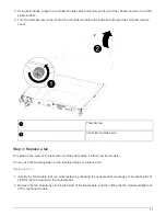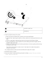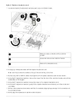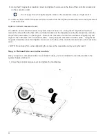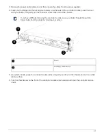
The controller module begins to boot as soon as it is fully seated in the chassis. Be prepared to
interrupt the boot process.
The controller module should be fully inserted and flush with the edges of the chassis.
3. Cable the management and console ports only, so that you can access the system to perform the tasks in
the following sections.
You will connect the rest of the cables to the controller module later in this procedure.
Step 5: Run diagnostics
After you have replaced a component in your system, you should run diagnostic tests on that component.
Your system must be at the LOADER prompt to start diagnostics.
All commands in the diagnostic procedures are issued from the controller where the component is being
replaced.
Steps
1. If the controller to be serviced is not at the LOADER prompt, reboot the controller:
system node halt
-node node_name
After you issue the command, you should wait until the system stops at the LOADER prompt.
2. At the LOADER prompt, access the special drivers specifically designed for system-level diagnostics to
function properly:
boot_diags
3. Select
Scan System
from the displayed menu to enable running the diagnostics tests.
4. Select
Test system
from the displayed menu to run diagnostics tests.
5. Proceed based on the result of the preceding step:
◦
If the scan show problems, correct the issue, and then rerun the scan.
◦
If the scan reported no failures, select Reboot from the menu to reboot the system.
Step 6: Return the failed part to NetApp
Return the failed part to NetApp, as described in the RMA instructions shipped with the kit. See the
Replace a power supply - FAS500f
Replacing a power supply involves disconnecting the target power supply (PSU) from the
power source, unplugging the power cable, removing the old PSU and installing the
replacement PSU, and then reconnecting it to the power source.
• The power supplies are redundant and hot-swappable.
• This procedure is written for replacing one power supply at a time.
71

