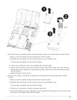
8. Push firmly on the fan module cam handle so that it is seated all the way into the chassis.
The cam handle raises slightly when the fan module is completely seated.
9. Swing the cam handle up to its closed position, making sure that the cam handle release latch clicks into
the locked position.
The fan LED should be green after the fan is seated and has spun up to operational speed.
10. Repeat these steps for the remaining fan modules.
Step 3: Replace a chassis from within the equipment rack or system cabinet
You must remove the existing chassis from the equipment rack or system cabinet before you can install the
replacement chassis.
Steps
1. Remove the screws from the chassis mount points.
2. With two people, slide the old chassis off the rack rails in a system cabinet or equipment rack, and then set
it aside.
3. If you are not already grounded, properly ground yourself.
4. Using two people, install the replacement chassis into the equipment rack or system cabinet by guiding the
chassis onto the rack rails in a system cabinet or equipment rack.
5. Slide the chassis all the way into the equipment rack or system cabinet.
6. Secure the front of the chassis to the equipment rack or system cabinet, using the screws you removed
from the old chassis.
7. If you have not already done so, install the bezel.
Step 4: Install the controller modules
After you install the controller modules into the new chassis, you need to boot it to a state where you can run
the diagnostic test.
For HA pairs with two controller modules in the same chassis, the sequence in which you install the controller
module is especially important because it attempts to reboot as soon as you completely seat it in the chassis.
Steps
1. Align the end of the controller module with the opening in the chassis, and then gently push the controller
module halfway into the system.
Do not completely insert the controller module in the chassis until instructed to do so.
2. Recable the console to the controller module, and then reconnect the management port.
3. Complete the installation of the controller module:
a. Plug the power cord into the power supply, reinstall the power cable locking collar, and then connect
the power supply to the power source.
b. Using the locking latches, firmly push the controller module into the chassis until the locking latches
begin to rise.
470


