Web Graphical User In-
terface (GUI) for ESMS
182
Event Filter Tab
A PEF implementation is recommended to provide at least 16 entries in the event filter table. A
subset of these entries should be pre-configured for common system failure events, such as over-
temperature, power system failure, fan failure events, etc. Remaining entries can be made avail-
able for ‘OEM’ or System Management Software configured events. Note that individual entries
can be tagged as being reserved for system use - so this ratio of pre-configured entries to run-time
configurable entries can be reallocated if necessary.
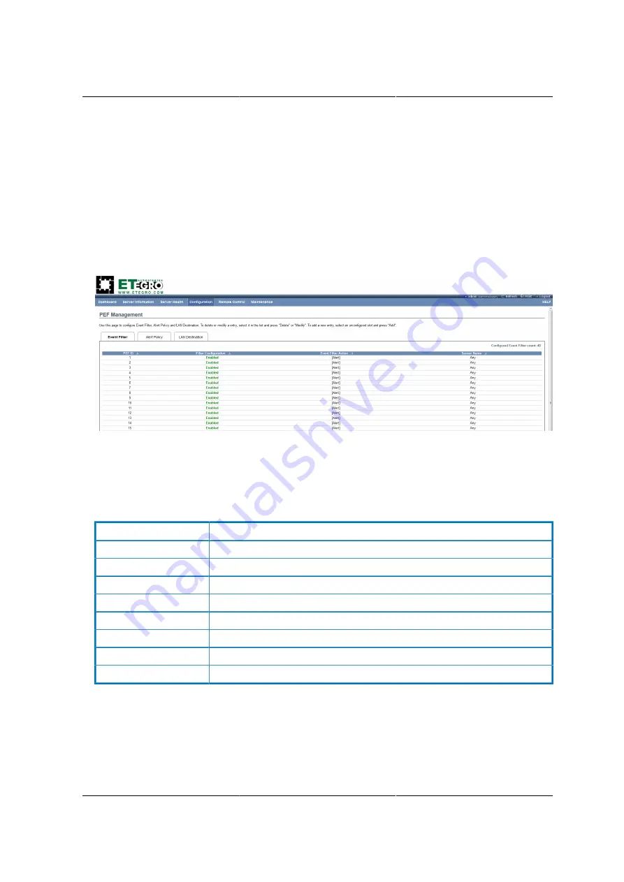
Figure 8.21. PEF Management – Event Filter
The fields of PEF Management – Event Filter Tab are explained below.
This page contains the list of configured PEF’s.
Table 8.12. PET Management - Event Filter
ITEM
DESCRIPTION
PEF ID
This field displays the ID for the newly configured PEF entry (read-only).
Filter configuration
Check box to enable the PEF settings.
Event Filter Action
Check box to enable PEF Alert action. This is a mandatory field.
Event Severity
To choose any one of the Event severity from the list.
Sensor Name
To choose the particular sensor from the sensor list.
Add
To add the new event filter entry and return to Event filter list.
Modify
To modify the existing entries.
Cancel
To cancel the modification and return to Event filter list.
Procedure:
1. Click the
Event Filter
Tab to configure the event filters in the available slots
2. To Add an Event Filter entry, select a free slot and click
Modify
to open the Modify event Filter
entry Page. A sample screenshot of Modify Event Filter Page is in seen the screenshot below.
Summary of Contents for Demos R130 M2
Page 1: ...Netberg Demos R130 M2 server...
Page 2: ...Netberg Demos R130 M2 server...
Page 11: ...Netberg Demos R130 M2 server xi 9 5 Aligning the Rails 222...
Page 14: ...1 Chapter 1 Netberg Demos R130 M2 server...
Page 31: ...Netberg Demos R130 M2 server 18 On HDD failure HDD Fault Amber Off No failure detected...
Page 32: ...19 Chapter 2 Installing hardware...
Page 57: ...Installing hardware 44 Figure 2 36 Installing the Air Duct...
Page 60: ...Installing hardware 47 Figure 2 40 Connecting the Fan Assembly Cables...
Page 143: ...130 Chapter 6 Server Management Software...
Page 169: ...156 Chapter 8 Web Graphical User Interface GUI for ESMS...
Page 230: ...217 Chapter 9 Rail Kit Assembly...
Page 236: ...223 Chapter 10 Troubleshooting...


