Installing hardware
57
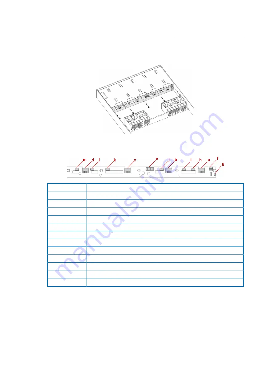
Figure 2.55. Installing the 3.5” HDD Backplane Screws
3. Connect the following cables to the HDD BP:
Figure 2.56. HDD BP Connectors
a.
Device 0 Connector connect to HDD 0
b.
Device 1 Connector connect to HDD 1
c.
Device 2 Connector connect to HDD 2
d.
Device 3 Connector connect to HDD 3
e.
10 pin Power connector for BP with +12V, +5V, +3.3V
f.
IPMB connector lining to on board BMC controller FAN Speed
g.
SGPIO connector for HDD LED Decode.
h.
System FAN 0 for CPU 0 Block
i.
System FAN 1 for CPU 0 Block
j.
System FAN 2 for CPU 0 Block
k.
System FAN 3 for CPU 1 Block
l.
System FAN 4 for CPU 1 Block
m.
System FAN 5 for CPU 1 Block
Summary of Contents for Demos R130 M2
Page 1: ...Netberg Demos R130 M2 server...
Page 2: ...Netberg Demos R130 M2 server...
Page 11: ...Netberg Demos R130 M2 server xi 9 5 Aligning the Rails 222...
Page 14: ...1 Chapter 1 Netberg Demos R130 M2 server...
Page 31: ...Netberg Demos R130 M2 server 18 On HDD failure HDD Fault Amber Off No failure detected...
Page 32: ...19 Chapter 2 Installing hardware...
Page 57: ...Installing hardware 44 Figure 2 36 Installing the Air Duct...
Page 60: ...Installing hardware 47 Figure 2 40 Connecting the Fan Assembly Cables...
Page 143: ...130 Chapter 6 Server Management Software...
Page 169: ...156 Chapter 8 Web Graphical User Interface GUI for ESMS...
Page 230: ...217 Chapter 9 Rail Kit Assembly...
Page 236: ...223 Chapter 10 Troubleshooting...


