


Safety Information
3
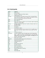
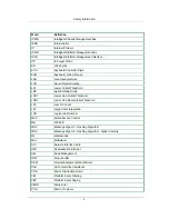
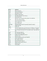
1.2. Acronyms
Word
Definition
A/D
Analog to Digital
ACPI
Advanced Configuration and Power Interface
ASF
Alerting Standard Forum
Asserted
Active-high (positive true) signals are asserted when in the high electrical
state (near power potential). Active-low (negative true) signals are asserted
when in the low electrical state (near ground potential).
BIOS
Basic Input/Output System
BIST
Built-In Self Test
BMC
At the heart of the IPMI architecture is a microcontroller called the Baseboard
management controller (BMC)
Bridge
Circuitry connecting one computer bus to another, allowing an agent on one
to access the other
BSP
Bootstrap processor
Byte
8-bit quantity
CLI
Command Line Interface
CMOS
In terms of this specification, this describes the PC-AT compatible region of
battery-backed 128 bytes of memory, which normally resides on the base-
board
CPU
Central Processing Unit
Deasserted
A signal is deasserted when in the inactive state. Active-low signal names
have "_L" appended to the end of the signal mnemonic. Active-high signal
names have no "_L" suffix. To reduce confusion when referring to active-high
and active-low signals, the terms one/zero, high/low, and true/false are not
used when describing signal states.
DTC
Data Transfer Controller
EEPROM
Electrically Erasable Programmable Read-Only Memory
EMP
Emergency Management Port
FRU
Field Replaceable Unit
GB
1024 MB.
GPIO
General Purpose Input/Out
HSC
Hot-Swap Controller
Hz
Hertz (1 cycle/second)
I2C
Inter-Integrated Circuit bus
IANA
Internet Assigned Numbers Authority
IBF
Input buffer
ICH
I/O Controller Hub
Summary of Contents for Demos R420 M2
Page 1: ...Netberg Demos R420 M2 server User manual...
Page 2: ...Netberg Demos R420 M2 server User manual...
Page 12: ...1 Chapter 1 Safety Information...
Page 19: ...8 Chapter 2 About the Server...
Page 32: ...21 Chapter 3 Installing Hardware...
Page 93: ...82 Chapter 4 Connectors...
Page 95: ...Connectors 84 Figure 4 1 Mainboard Overview...
Page 108: ...Connectors 97 4 9 Sensor Board Connectors Figure 4 13 Sensor Board 1 I2C Connector...
Page 109: ...98 Chapter 5 Cable Routing...
Page 110: ...Cable Routing 99 5 1 Cable Routing for 12 x 3 5 Hard Drives Configuration...
Page 111: ...Cable Routing 100 5 2 Cable Routing for 24 x 2 5 Hard Drives Configuration...
Page 112: ...101 Chapter 6 BIOS...
Page 125: ...BIOS 114 6 3 1 5 CPU Advanced PM Tuning...
Page 172: ...BIOS 161 6 4 2 View FRU Information...
Page 176: ...BIOS 165 Menu Fields Settings Comments Network Device BBS Priorities 1...
Page 182: ...171 Chapter 7 Rail Kit Assembly...
Page 186: ...Rail Kit Assembly 175 Figure 7 3 Tightening the Thumbscrews...
Page 187: ...176 Chapter 8 Troubleshooting...


