Server Safety Information
194
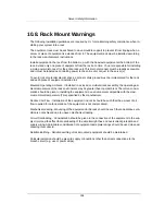
10.8. Rack Mount Warnings
The following installation guidelines are required by UL for maintaining safety compliance when in-
stalling your system into a rack.
The equipment rack must be anchored to an unmovable support to prevent it from tipping when a
server or piece of equipment is extended from it. The equipment rack must be installed according
to the rack manufacturer’s instructions.
Install equipment in the rack from the bottom up, with the heaviest equipment at the bottom of the
rack. Extend only one piece of equipment from the rack at a time. You are responsible for installing
a main power disconnect for the entire rack unit. This main disconnect must be readily accessible,
and it must be labeled as controlling power to the entire unit, not just to the server(s).
To avoid risk of potential electric shock, a proper safety ground must be implemented for the rack
and each piece of equipment installed in it.
Elevated Operating Ambient - If installed in a closed or multiunit rack assembly, the operating am-
bient temperature of the rack environment may be greater than room ambient. Therefore, consid-
eration should be given to installing the equipment in an environment compatible with the maxi-
mum ambient temperature (Tma) specified by the manufacturer.
Reduced Air Flow - Installation of the equipment in a rack should be such that the amount of air
flow required for safe operation of the equipment is not compromised.
Mechanical Loading - Mounting of the equipment in the rack should be such that a hazardous con-
dition is not achieved due to uneven mechanical loading.
Circuit Overloading - Consideration should be given to the connection of the equipment to the sup-
ply circuit and the effect that overloading of the circuits might have on overcurrent protection and
supply wiring. Appropriate consideration of equipment nameplate ratings should be used when ad-
dressing this concern.
Reliable Earthing - Reliable earthing of rack-mounted equipment should be maintained.
Particular attention should be given to supply connections other than direct connections to the
branch circuit (e.g. use of power strips).
Summary of Contents for Demos R420 M2
Page 1: ...Netberg Demos R420 M2 server User manual...
Page 2: ...Netberg Demos R420 M2 server User manual...
Page 12: ...1 Chapter 1 Safety Information...
Page 19: ...8 Chapter 2 About the Server...
Page 32: ...21 Chapter 3 Installing Hardware...
Page 93: ...82 Chapter 4 Connectors...
Page 95: ...Connectors 84 Figure 4 1 Mainboard Overview...
Page 108: ...Connectors 97 4 9 Sensor Board Connectors Figure 4 13 Sensor Board 1 I2C Connector...
Page 109: ...98 Chapter 5 Cable Routing...
Page 110: ...Cable Routing 99 5 1 Cable Routing for 12 x 3 5 Hard Drives Configuration...
Page 111: ...Cable Routing 100 5 2 Cable Routing for 24 x 2 5 Hard Drives Configuration...
Page 112: ...101 Chapter 6 BIOS...
Page 125: ...BIOS 114 6 3 1 5 CPU Advanced PM Tuning...
Page 172: ...BIOS 161 6 4 2 View FRU Information...
Page 176: ...BIOS 165 Menu Fields Settings Comments Network Device BBS Priorities 1...
Page 182: ...171 Chapter 7 Rail Kit Assembly...
Page 186: ...Rail Kit Assembly 175 Figure 7 3 Tightening the Thumbscrews...
Page 187: ...176 Chapter 8 Troubleshooting...

