About the Server
18
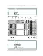
No.
Description
14
System Health LED
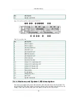
Figure 2.8. Back View with Two Nodes (with OCP SFP+ NIC)
Table 2.8. System Rear View
No.
Description
1
Power Supply 2
2
Power Supply 1
3
Rear Dual USB Port
4
10G NIC 1 port
5
SAS External Port 1
6
BMC Reset Button
7
SAS External Port 0
8
VGA Connector
9
Dual SSD OS Disks
10
10Gbe NIC 1 Link/Activity LED
11
10Gbe NIC 0 Link/Activity LED
12
10Gbe NIC 0 Speed LED
13
10Gbe NIC 1 Speed LED
14
Power Button
15
ID LED/Button
16
Management Port
17
NIC Port 0
18
System Health LED
2.4.4. Buttons and System LED description
This server is equipped with system LED indicators, and buttons located on the front panels. The
front panel status LEDs allow constant monitoring of basic system functions while the server is op-
erating. These LEDs provide visual cues to the status of power and ID of each node.
Summary of Contents for Demos R420 M2
Page 1: ...Netberg Demos R420 M2 server User manual...
Page 2: ...Netberg Demos R420 M2 server User manual...
Page 12: ...1 Chapter 1 Safety Information...
Page 19: ...8 Chapter 2 About the Server...
Page 32: ...21 Chapter 3 Installing Hardware...
Page 93: ...82 Chapter 4 Connectors...
Page 95: ...Connectors 84 Figure 4 1 Mainboard Overview...
Page 108: ...Connectors 97 4 9 Sensor Board Connectors Figure 4 13 Sensor Board 1 I2C Connector...
Page 109: ...98 Chapter 5 Cable Routing...
Page 110: ...Cable Routing 99 5 1 Cable Routing for 12 x 3 5 Hard Drives Configuration...
Page 111: ...Cable Routing 100 5 2 Cable Routing for 24 x 2 5 Hard Drives Configuration...
Page 112: ...101 Chapter 6 BIOS...
Page 125: ...BIOS 114 6 3 1 5 CPU Advanced PM Tuning...
Page 172: ...BIOS 161 6 4 2 View FRU Information...
Page 176: ...BIOS 165 Menu Fields Settings Comments Network Device BBS Priorities 1...
Page 182: ...171 Chapter 7 Rail Kit Assembly...
Page 186: ...Rail Kit Assembly 175 Figure 7 3 Tightening the Thumbscrews...
Page 187: ...176 Chapter 8 Troubleshooting...

