background image

Installing Hardware

30

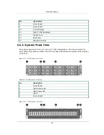
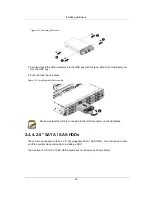
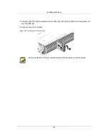
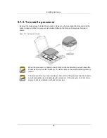
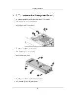
Figure 3.13. 2.5” SATA / SAS HDD Locations

Take note of the drive tray orientation before sliding it out. The tray will not fit back into

the bay if inserted incorrectly.

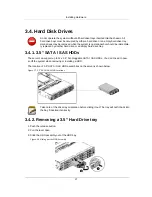
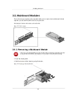
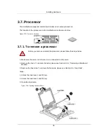
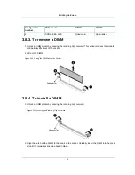
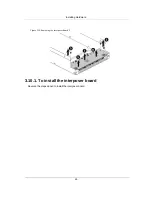
3.4.5. Removing a 2.5” Hard Drive tray

1. Push the release button.

2. Pull the lever open.

3. Slide the HDD assembly out of the HDD bay.

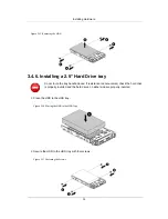
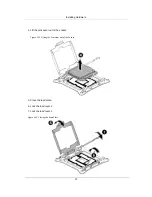
Figure 3.14. Sliding out the HDD Assembly

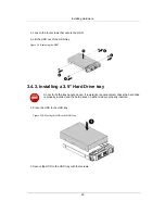
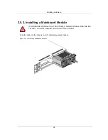
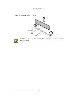
4. Loosen the four screws that secure the HDD.

5. Lift the HDD out of the HDD tray.

Summary of Contents for Demos R420 M2

Page 1: ...Netberg Demos R420 M2 server User manual...

Page 2: ...Netberg Demos R420 M2 server User manual...

Page 3: ...t 26 3 4 Hard Disk Drives 27 3 4 1 3 5 SATA SAS HDDs 27 3 4 2 Removing a 3 5 Hard Drive tray 27 3 4 3 Installing a 3 5 Hard Drive tray 28 3 4 4 2 5 SATA SAS HDDs 29 3 4 5 Removing a 2 5 Hard Drive tra...

Page 4: ...distribution boards 58 3 17 2 To install the power distribution board 60 3 18 System Fans 61 3 18 1 To remove a system fan 61 3 18 2 To install a system fan 61 3 18 3 To remove the fan control board 6...

Page 5: ...lity 102 6 1 1 Entering BIOS Setup 102 6 1 2 Main features 102 6 1 3 Setup Page 102 6 1 4 Keyboard Commands 103 6 1 5 Menu Selection Bar 105 6 1 6 Server Platform Setup Utility Screens 105 6 2 Main 10...

Page 6: ...m Settings 153 6 3 12 Network Stack Configuration 154 6 3 13 CSM Configuration 155 6 3 14 Trusted Computing 156 6 3 15 USB Configuration 157 6 4 Server Management 159 6 4 1 System Event Log 160 6 4 2...

Page 7: ...ses 188 10 3 Site Selection 189 10 4 Equipment Handling Practices 190 10 5 Power and Electrical Warnings 191 10 6 Power Cord Warnings 192 10 7 System Access Warnings 193 10 8 Rack Mount Warnings 194 1...

Page 8: ...Fastening the Screws 29 3 12 Installing the HDD Assembly 29 3 13 2 5 SATA SAS HDD Locations 30 3 14 Sliding out the HDD Assembly 30 3 15 Removing the HDD 31 3 16 Placing the HDD to the HDD Tray 31 3 1...

Page 9: ...Fan Control Board 62 3 61 Upper Middle Plane Location 63 3 62 Lower NIC Middle Plane Location 63 3 63 Lower NTB Middle Plane Location 64 3 64 Removing the Upper Middle Plane 64 3 65 Removing the Midd...

Page 10: ...TB Middle Plane 91 4 8 Power Distribution Board 92 4 9 Rear HDD Backplane 93 4 10 Expander Board 94 4 11 Fan Control Board 95 4 12 Interposer Board 96 4 13 Sensor Board 97 6 1 Main Screen 106 6 2 Adva...

Page 11: ...tem Front View 17 2 7 System Rear View 17 2 8 System Rear View 18 2 9 Front Panel Buttons and LEDs 19 2 10 Rear Panel Power LEDs 19 2 11 HDD LED Definition 20 2 12 Front Panel LED Definition 20 6 1 BI...

Page 12: ...1 Chapter 1 Safety Information...

Page 13: ...d files Enter type face denotes keyboard keys Warning information appears before the text it references and should not be ignored as the content may prevent damage to the device CAUTIONS APPEAR BEFORE...

Page 14: ...e Interface CMOS In terms of this specification this describes the PC AT compatible region of battery backed 128 bytes of memory which normally resides on the base board CPU Central Processing Unit De...

Page 15: ...g Diode LNCT Lower Non Critical Threshold LNRT Lower Non Recoverable Threshold LPC Low Pin Count LSI Large Scale Integration LUN Logical Unit Number MAC Media Access Control MB 1024 KB MD2 Message Dig...

Page 16: ...d Only Memory SEL System Event Log SERR System Error SMBus A two wire interface based on the I2C protocol The SMBus is a low speed bus that provides positive addressing for devices as well as bus arbi...

Page 17: ...e opening it Otherwise personal injury or equipment damage can result Electrostatic discharge ESD and ESD protection ESD can damage drives boards and other parts We recommend that you perform all proc...

Page 18: ...ability or fitness for any particular purpose Furthermore the manufac turer reserves the right to revise this publication and to make changes from time to time in the con tent hereof without obligatio...

Page 19: ...8 Chapter 2 About the Server...

Page 20: ...ument is for the person who installs administers and troubleshoots servers and storage systems Netberg assumes you are qualified in the servicing of computer equipment and trained in recognizing hazar...

Page 21: ...ns that identify these features and specifications Figure 2 1 3 5 HDD System Front View Figure 2 2 2 5 HDD System Front View Table 2 1 Major Features Chassis 2U rack mounted chassis Power 2 x 1400W re...

Page 22: ...icrosoft Storage Spaces HW RAID Options LSI Syncro CS Cluster in a box Solution optional Network 2 Intel 10G SFP ports option 2 Intel 10G Base T ports option Management Port 1 Dedicated management 10...

Page 23: ...About the Server 12 Form Factor 2 independent nodes in a 2U chassis Humidity Operating System 20 80 Non operating System with package 10 90...

Page 24: ...About the Server 13 2 3 Package Contents The following list includes the package components 1 x 2U chassis system 1 x Power cord 1 x Rail kit...

Page 25: ...e major component parts of these two variants 2 4 1 System Figure 2 3 3 5 HDD System Overview Table 2 3 Component Overview No Description 1 Power Suply 2 Nodes 3 Power Distribution Boards 4 FCB Fan Co...

Page 26: ...11 System Fans 12 Interposers 13 Expansion boards Figure 2 4 2 5 HDD System Overview Table 2 4 Component Overview No Description 1 Power Suply 2 Nodes 3 Power Distribution Boards 4 FCB Fan Control Bo...

Page 27: ...m supports up to 12 x 3 5 or 24 x 2 5 HDD configurations The front view of this 2U server allows easy access to HDDs Also the front panel with buttons and system LEDs is located on the front Figure 2...

Page 28: ...view includes the connectors of the external system devices Figure 2 7 Back View with Two Nodes with OCP 1G 10G Base T NIC Table 2 7 System Rear View No Description 1 Power Supply 2 2 Power Supply 1 3...

Page 29: ...10 10Gbe NIC 1 Link Activity LED 11 10Gbe NIC 0 Link Activity LED 12 10Gbe NIC 0 Speed LED 13 10Gbe NIC 1 Speed LED 14 Power Button 15 ID LED Button 16 Management Port 17 NIC Port 0 18 System Health...

Page 30: ...n 1 ID Button for Node 1 2 Power Button for Node 1 3 ID Button for Node 2 4 Power Button for Node 2 The back view LED information displays details regarding the AC power LED Figure 2 11 Rear Panel Pow...

Page 31: ...lue Purple Blue Purple Blink Consistency Check SES Table 2 12 Front Panel LED Definition Name Color Condtion Description Green On Amber Off Power On S0 S1 Green Off Amber Off Power Off S4 S5 Green Off...

Page 32: ...21 Chapter 3 Installing Hardware...

Page 33: ...to a power supply can be extreme ly dangerous Follow the guidelines below to avoid personal injury or damage to the server Always disconnect the server from the power outlet whenever you are working...

Page 34: ...the screw on the chassis cover 2 Press the button along the direction of the arrow 3 Simultaneously slide the cover horizontally to the back and remove it Figure 3 1 Removing Top Cover 3 2 2 Installin...

Page 35: ...are 24 Figure 3 2 Sliding the Chassis Cover to the Front 2 Secure the chassis cover with one screw Figure 3 3 Installing Screws This system must be operated with the chassis cover installed to ensure...

Page 36: ...ancy is supported on design with a throttling feature to downgrade pow er consumption when a PSU is faulty or has been removed A single faulty PSU can be replaced without system shut down DISCONNECT T...

Page 37: ...the Power Supply 3 3 2 Installing a Power Supply Unit Figure 3 6 Installing a Power Supply Unit Insert the replacement power supply firmly into the bay The retaining clip should snap Connect the AC p...

Page 38: ...3 5 SATA SAS HDDs The server can support up to 12 x 3 5 hot pluggable SATA SAS HDDs You don t need to pow er off the system when removing or installing a HDD The location of 3 5 SATA SAS HDD assemblie...

Page 39: ...3 4 3 Installing a 3 5 Hard Drive tray Do not force the tray handle closed If resistance is encountered check the hard drive is properly inserted and the hard drives on either side are properly inser...

Page 40: ...h the lever back in place Figure 3 12 Installing the HDD Assembly Make sure that the HDD is connected to the HDD connector on the backplane 3 4 4 2 5 SATA SAS HDDs The server can support up to 24 x 2...

Page 41: ...out The tray will not fit back into the bay if inserted incorrectly 3 4 5 Removing a 2 5 Hard Drive tray 1 Push the release button 2 Pull the lever open 3 Slide the HDD assembly out of the HDD bay Fi...

Page 42: ...tray handle closed If resistance is encountered check the hard drive is properly inserted and the hard drives on either side are properly inserted 1 Place the HDD to the HDD tray Figure 3 16 Placing...

Page 43: ...the HDD assembly into the HDD bay with the lever lifted until it completely en ters the HDD bay 4 Push the lever back in place Figure 3 18 Installing the HDD Assembly Make sure that the HDD is connec...

Page 44: ...The location of node on the server is shown below Figure 3 19 Node Locations 3 5 1 Removing a Mainboard Module There are no restraining latches on the modules When removing a module make sure to suppo...

Page 45: ...a Mainboard Module IF MAINBOARD MODULE IS NOT PROVIDED A DUMMY MODULE MUST BE INS TALLED TO ALLOW PROPER COOLING OF THE SYSTEM Push the node into the chassis until it s completely seated in place Fig...

Page 46: ...inboard Module 3 Remove the fan duct To remove the fan duct please see Section 3 14 Fan Duct 4 Disconnect all necessary cables Steps 1 Loosen the four securing screws 2 Lift the heat sink up from the...

Page 47: ...remove or install the processor please follow the steps below 1 Make sure the server is not turned on or connected to AC power 2 Remove the node To remove the node please see Section 3 5 1 Removing a...

Page 48: ...Hardware 37 4 Lift the processor out of the socket Figure 3 25 Lifting the Processor out of the Socket 5 Close the load plate 6 Lock the load lever 2 7 Lock the load lever 1 Figure 3 26 Closing the L...

Page 49: ...ows Figure 3 27 Placing the Processor When the processor is in place press it firmly on the socket while you push down the socket lever to secure the processor The lever clicks on the socket indicatin...

Page 50: ...otherboard is shown below Figure 3 28 Location of System Memory There are 16 DIMMs on the motherboard to support the processor The DIMM sequence of the DIMM sockets is respectively shown below Figure...

Page 51: ...l Configuration number POR speed DIMM2 DIMM1 DIMM0 1 DDR4 1866 1600 Empty Empty Quad rank 2 DDR4 1866 1600 Empty Quad rank Quad rank 3 DDR4 1600 1333 Quad rank Quad rank Quad rank 3 8 2 DDR4 2 slots p...

Page 52: ...ases the module and partially lifts it out of the socket 2 Lift out the DIMM Figure 3 30 Lifting the DIMM out of the Socket 3 8 4 To install a DIMM 1 Unlock a DIMM socket by pressing the retaining cli...

Page 53: ...Installing Hardware 42 Figure 3 32 Inserting the DIMM into the Socket DIMMs fit in only one direction DO NOT force a DIMM into the socket to avoid dam aging the DIMM...

Page 54: ...Board Location Before you remove or install the interposer board please follow the steps below 1 Make sure the server is not turned on or connected to AC power 2 Remove the nodes To remove the nodes s...

Page 55: ...bracket 2 Lift the interposer board 1 from the bracket Figure 3 34 Removing the interposer Board 1 3 Loosen the screws that secure the bracket 4 Lift the bracket from the node assembly Figure 3 35 Rem...

Page 56: ...Installing Hardware 45 Figure 3 36 Removing the interposer Board 2 3 10 1 To install the interposer board Reverse the steps above to install the interposer board...

Page 57: ...er board please follow the steps below 1 Make sure the server is not turned on or connected to AC power 2 Remove the nodes To remove the nodes see Section 3 5 1 Removing a Mainboard Module 3 Disconnec...

Page 58: ...crews that secure the expander board 4 Press and remove the expander board in the direction as shown below Figure 3 39 Removing the Expander Board 3 11 2 To install the expander board Reverse the step...

Page 59: ...embly out of the HDD cage Figure 3 40 Removing the Rear HDD Assembly 4 Open the locking tab on the HDD carrier 5 Press on the HDD to detach it from the HDD carrier Figure 3 41 Removing the Rear HDD 3...

Page 60: ...r HDD backplane Before you remove or install the rear HDD backplane please follow the steps below 1 Make sure the server is not turned on or connected to AC power 2 Remove the node To remove the node...

Page 61: ...HDD Backplane Bracket 3 Loosen the screw that secures the rear HDD backplane 4 Remove the rear HDD backplane Figure 3 45 Removing the Rear HDD Backplane 3 12 4 To install the rear HDD backplane Rever...

Page 62: ...emove the expansion card assembly and rear HDD assembly To remove the rear HDD as sembly see Section 3 12 1 To remove the rear HDD 4 Disconnect all necessary cables 3 13 1 To remove the expansion card...

Page 63: ...rver is not turned on or connected to AC power 2 Remove the node To remove the node see Section 3 5 1 Removing a Mainboard Module 3 Remove the expansion card assembly and rear HDD assembly To remove t...

Page 64: ...Installing Hardware 53 Figure 3 48 Removing the Riser Card 3 13 4 To install the X16 Riser Card Reverse the steps above to install the riser card...

Page 65: ...ke sure the server is not turned on or connected to AC power 2 Remove the chassis cover To remove the chassis cover see Section 3 2 Top Cover 3 Remove the node To remove the node see Section 3 5 1 Rem...

Page 66: ...card assembly and rear HDD assembly To remove the expansion card assembly and rear HDD assembly see Section 3 12 1 To remove the rear HDD 4 Remove the fan duct To remove the fan duct see Section 3 14...

Page 67: ...ate please follow the steps below 1 Make sure the server is not turned on or connected to AC power 2 Remove the chassis cover To remove the chassis cover see Section 3 2 Top Cover 3 Disconnect all nec...

Page 68: ...Installing Hardware 57 3 16 2 To install the strong plate Reverse the steps above to install the strong plate...

Page 69: ...move or install the power distribution boards please follow the steps below 1 Make sure the server is not turned on or connected to AC power 2 Remove the chassis cover To remove the chassis cover see...

Page 70: ...moving the Upper Power Distribution Board 3 Remove the bridge card Figure 3 56 Removing the Bridge Card 4 Loosen the four screws that secure the lower power distribution board 5 Lift the lower power d...

Page 71: ...Installing Hardware 60 Figure 3 57 Removing the Lower Power Distribution Board 3 17 2 To install the power distribution board Reverse the steps above to install the power distribution boards...

Page 72: ...f system fans is shown below Figure 3 58 System Fan Location Before you remove or install a system fan please follow the steps below 1 Make sure the server is not turned on or connected to the AC powe...

Page 73: ...n the screw that secures the fan control board 2 Remove the fan control board out of the chassis along the direction of the arrow Figure 3 60 Removing the Fan Control Board 3 18 4 To install the fan c...

Page 74: ...ower middle plane supports NIC or NTB middle planes based on the storage OS The location of upper middle plane is shown below Figure 3 61 Upper Middle Plane Location The location of lower NIC middle p...

Page 75: ...hassis cover see Section 3 2 Top Cover 3 Remove the node To remove the node see Section 3 5 1 Removing a Mainboard Module 4 Disconnect all the necessary cables 3 19 1 To remove the middle planes 1 Loo...

Page 76: ...Plane Bracket 5 Loosen the screws that secure the lower middle plane 6 Remove the lower middle plane out of the chassis Figure 3 66 Removing the Lower Middle Plane 3 19 2 To install the middle planes...

Page 77: ...location of 3 5 SATA SAS HDD backplane is shown below Figure 3 67 3 5 HDD Backplane Location Before you remove or install the SATA SAS HDD backplane please follow the steps below 1 Make sure the serve...

Page 78: ...Screws 2 Remove the screws that secure the front panels 3 Remove the HDD cage along the direction of the arrow Figure 3 69 Removing the HDD Cage 4 Loosen the screws that secure the backplane to the HD...

Page 79: ...Installing Hardware 68 Figure 3 70 Removing the backplane 3 20 2 To install the backplane Reverse the steps above to install the backplane...

Page 80: ...ation of 2 5 SATA SAS HDD backplane is shown below Figure 3 71 24 x 2 5 HDD Backplane Location Before you remove or install the SATA SAS HDD backplane please follow the steps below 1 Make sure the ser...

Page 81: ...the screws that secure the front panels 3 Remove the HDD cage along the direction of the arrow Figure 3 73 Removing the HDD Cage 4 Loosen the screws that secure the bridge board to the bridge board b...

Page 82: ...en the screws that secure the bridge board bracket to the HDD cage 7 Remove the bridge board bracket from the HDD cage Figure 3 75 Removing the Bridge Board Bracket 8 Loosen the screws that secure the...

Page 83: ...Installing Hardware 72 Figure 3 76 Removing the Backplane 3 21 2 To install the backplane Reverse the steps above to install the backplane...

Page 84: ...elow 1 Make sure the server is not turned on or connected to AC power 2 Remove the chassis cover To remove the chassis cover see Section 3 2 Top Cover 3 Remove the node To remove the node see Section...

Page 85: ...Installing Hardware 74 3 22 2 To install the HBA card 1 Align and press down the HBA card until it clicks in place and is secured by the locking clips Figure 3 79 Installing the HBA Card...

Page 86: ...ll the HBA card please follow the steps below 1 Make sure the server is not turned on or connected to AC power 2 Remove the chassis cover To remove the chassis cover see Section 3 2 Top Cover 3 Remove...

Page 87: ...81 Removing the OCP Card 3 23 2 To install the OCP card 1 Align the OCP card in the direction as shown below 2 Press down the OCP card until it clicks in place and is secured by the locking clips Figu...

Page 88: ...Figure 3 83 Front Panel Location 3 24 1 To remove the front panel 1 Loosen the screws that secure the front panel assembly 2 Remove the frong panel assembly out of the chassis Figure 3 84 Removing th...

Page 89: ...Installing Hardware 78 Figure 3 85 Removing the Front Panel 3 24 2 To install the front panel Reverse the steps above to install the front panel...

Page 90: ...Location 3 25 1 To remove the sensor board of 12 x 3 5 HDD Server Before you remove or install the sensor board please follow the steps below 1 Make sure the server is not turned on or connected to t...

Page 91: ...erver Before you remove or install the sensor board please follow the steps below 1 Make sure the server is not turned on or connected to the AC power 2 Remove the chassis cover To remove the chassis...

Page 92: ...Installing Hardware 81 Figure 3 89 Removing the Sensor Board 3 25 4 To install the sensor board of 24 x 2 5 HDD Server Reverse the steps above to install the sensor board...

Page 93: ...82 Chapter 4 Connectors...

Page 94: ...Connectors 83 4 1 Motherboard Connectors This section provides information on basic connectors on system mainboard...

Page 95: ...Connectors 84 Figure 4 1 Mainboard Overview...

Page 96: ...J37 15 Mezz Slot 1 J26 16 Mezz Slot 2 J57 17 SATA SGPIO Connector J41 18 BMC Debug Connector J44 19 Power Debug Header J70 20 TPM Connector J2 21 SGPIO Connector J71 22 BP LED Connector J72 23 DIMM S...

Page 97: ...ATA Connector 0 J32 40 BIOS Recovery Jumper J27 41 Intruder Header J53 42 Repeater I2C Connector J79 43 SATA DOM Power Connector J6 44 PCH SATA Connector 1 J34 45 PCH SATA Connector 2 5 J42 46 NMI Jum...

Page 98: ...6 8 12 PCIE Connectors 3 5 4 SAS NVMe HDD Connectors 9 11 13 SAS1 HDD Connectors 3 5 5 PCIE Connectors 9 11 14 SAS0 HDD Connectors 3 5 6 SAS1 HDD Connectors 9 11 15 PCIE Connectors 0 2 7 SAS0 HDD Con...

Page 99: ...NVMe Connectors 4 5 5 Power Connector 1 2 SAS HDD Connectors 6 9 SAS NVMe Connectors 10 11 6 Power Connector 2 3 SAS HDD Connectors 12 15 SAS NVMe Connectors 16 17 7 Bridge Board Connectors 4 SAS HDD...

Page 100: ...Connectors 4 5 10 PCIE Connectors 22 23 3 SAS0 HDD Connectors 8 15 11 SAS1 HDD Connectors 20 23 4 PCIE Connectors 10 11 12 SAS0 HDD Connectors 4 7 5 SAS0 HDD Connectors 20 23 13 SAS0 HDD Connectors 1...

Page 101: ...nnector 0 7 2 SAS1 HDD Connector 16 23 7 SAS0 HDD Connector 16 23 3 Power Connector for Node 1 8 SAS0 HDD Connector 8 15 4 SAS1 HDD Connector 8 15 9 SAS0 HDD Connector 0 7 5 Power Connector for Node 0...

Page 102: ...Connectors 91 4 3 3 NTB Middle Plane Figure 4 7 NTB Middle Plane LOCATION CONNECTOR 1 Power Connector for Node 1 3 FCB Connector 2 Power Connector for Node 0...

Page 103: ...Distribution Board Connectors Figure 4 8 Power Distribution Board LOCATION CONNECTOR 1 Bridge Board Connector 4 Main Power Connector for Mother board 2 HDD Backplane Power Connector 5 FCB Power Conne...

Page 104: ...nnectors 93 4 5 Rear HDD Backplane Connectors Figure 4 9 Rear HDD Backplane LOCATION CONNECTOR 1 Power Connector 3 SATA Connector 1 2 SATA Connector 2 4 LED Connector 5 HDD Connector 1 6 HDD Connector...

Page 105: ...Connectors 94 4 6 Expander Board Connectors Figure 4 10 Expander Board LOCATION CONNECTOR 1 UART Jumper 3 SAS External Port 1 2 SAS External Port 0...

Page 106: ...ECTOR 1 PMBUS Connector 8 Front Panel 1 Connector 2 HDD Backplane Connector 9 Motherboard 1 3 Connector 3 Fan Connector 3 10 Fan Connector 2 4 Fan Connector 4 11 Motherboard 2 4 Connector 5 ARM JTAG C...

Page 107: ...re 4 12 Interposer Board LOCATION CONNECTOR 1 Expander Upper Middle Plane Con nector 5 SAS HDD Connector 0 7 2 Expander Upper Middle Plane Con nector 6 SAS HDD Connector 8 15 3 Power Connector 7 SAS H...

Page 108: ...Connectors 97 4 9 Sensor Board Connectors Figure 4 13 Sensor Board 1 I2C Connector...

Page 109: ...98 Chapter 5 Cable Routing...

Page 110: ...Cable Routing 99 5 1 Cable Routing for 12 x 3 5 Hard Drives Configuration...

Page 111: ...Cable Routing 100 5 2 Cable Routing for 24 x 2 5 Hard Drives Configuration...

Page 112: ...101 Chapter 6 BIOS...

Page 113: ...tarted by pressing DEL or F2 during boot time when the logo is displayed When Quiet Boot is disabled the message press DEL or F2 to enter setup will be displayed on the diagnostics screen 6 1 2 Main f...

Page 114: ...sub menu or to display a pick list if a selected option has a value field or to select a sub field for mul ti valued features like time and date If a pick list is displayed the Enter key will select...

Page 115: ...8 Previous Val ues Pressing F8 makes the following message to appear Load Previous Values Yes No If Yes is highlighted and Enter is pressed all Setup fields are set to their previous values If No is h...

Page 116: ...f the tables indicates default values These values are not dis played in bold on the setup screen The bold text in this document is to serve as a reference point The Comments column provides additiona...

Page 117: ...ed unless an error has occurred If an error has occurred the Error Manager screen will be displayed instead Figure 6 1 Main Screen Table 6 3 Main Screen Fields Menu Fields Settings Comments Main Syste...

Page 118: ...several options On this screen the user selects the option that is to be configured Configurations are performed on the selected screen not directly on Advanced screen To access this screen from Main...

Page 119: ...Configuration Menu Fields Settings Comments Advanced Processor Configuration Hyper Threading ALL Enables Hyper Threading Software Method to Enable Disable Logical Processor threads Execute Disable Bit...

Page 120: ...Mode Extensions Adjacent Cache Prefetch MLC Spatial Prefetcher MSR 1A4h Bit 1 DCU Streamer Prefetcher DCU streamer prefetcher is an L1 da ta cache prefetcher MSR 1A4h 2 DCU IP Prefetcher DCU IP prefe...

Page 121: ...Figure 6 4 Advanced Power Management Configuration Menu Fields Settings Comments Advanced Processor Configuration Advanced Power Management Configuration Power Technology Enables the power management...

Page 122: ...ation Advanced Power Management Configuration CPU P State Control EIST P states When enabled OS sets CPU fre quency according load When dis abled CPU frequency is set at max non turbo P state coordina...

Page 123: ...ol Package C State limit Package C State limit CPU C3 report Enable Disable CPU C3 ACPI C2 report to OS Recommended to be disabled CPU C6 report Enable Disable CPU C6 ACPI C2 re port to OS Recommended...

Page 124: ...tate Control Menu Fields Settings Comments Advanced Processor Configuration Advanced Power Management Configuration CPU T State Control ACPI T States Enable Disable CPU throttling by OS Throttling red...

Page 125: ...BIOS 114 6 3 1 5 CPU Advanced PM Tuning...

Page 126: ...ystem chooses energy performance bias tuning Energy Performance BIAS setting Set Energy Performance BIAS which overrides OS setting Power Performance Switch MSR 1FCh Bit 24 PWR_PERF_TUNING_ENABLE_DYN_...

Page 127: ...h 58 6 3 2 QPI Configuration Menu Fields Settings Comments Advanced QPI Configuration Link Speed Mode Select the QPI link speed as either the POR speed Fast or default speed Slow Link Frequency Select...

Page 128: ...nts Advanced Memory Configuration Numa Enable or Disable Non uniform emory Access NUMA Enforce POR Enable to enforce POR restrictions for DDR4 frequency and voltage pro gramming Memory Frequency Maxim...

Page 129: ...MRC will not use SPD bytes 90 95 for LRDIMM Module Delay When Auto MRC will bound ary check the values and use default values if SPD is 0 or out of range Memory Type Selects the Memory type supported...

Page 130: ...dwidth al lowed for OLTT DIMM Temp Stat 92 Select DIMMTEMPSTAT as temp_mid or temp_hi Phase Shedding VR Static Phase Shedding Support PS0 full phase PS1 single phase typically 18A load PS2 fixed loss...

Page 131: ...ttling Configure Memory Electrical Throt tling 6 3 4 1 Memory Power Savings Advanced Options Menu Fields Settings Comments Advanced Memory Configuration Memory Thermal Memory Power Savings Advanced Op...

Page 132: ...e if enabled Sparing will be selected Lockstep x4 DIMMs Enable Disable Lockstep for x4 DIMMs Memory Rank Sparing Enable Disable Memory Rank Spar ing Multi Rank Sparing Set Multi Rank Sparing number Au...

Page 133: ...Disable Patrol Scrub Demand Scrub Enable Disable Demand Scrub Device Tagging Enable Disable Device Tagging 6 3 5 IIO Configuration Menu Fields Settings Comments Advanced IIO Configuration EV DFX Featu...

Page 134: ...de vices 6 3 5 1 IIO0 Configuration Menu Fields Settings Comments Advanced IIO Configuration IIO0 Configuration IOU2 IIO PCIe Port 1 Selects PCIe port Bifurcation for se lected slot s IOU0 IIO PCIe P...

Page 135: ...2 Socket 0 PcieD00F0 Port0 DMI Menu Fields Settings Comments Advanced IIO Configuration IIO0 Configuration Socket 0 PcieDxxFx Port xx Link Speed PCI E Port DeEmphasis De Emphasis control LNKCON2 6 for...

Page 136: ...uration Menu Fields Settings Comments Advanced IIO Configuration IIO1 Configuration IOU2 IIO PCIe Port 1 Selects PCIe port Bifurcation for se lected slot s IOU0 IIO PCIe Port 2 Selects PCIe port Bifur...

Page 137: ...ings Comments Advanced IIO Configuration IOAT Configuration Enable IOAT Control to enable disable IOAT de vices No Snoop No Snoop Enable Disable for each CB device Disable TPH TLP Processing Hint disa...

Page 138: ...Enable Disable Intel Virtualization Technology for Directed I O VT d by reporting the I O device assignment to VMM through DMAR ACPI Tables Interrupt Remapping Enable Disable VT_D Interrupt Remapping...

Page 139: ...BIOS 128 6 3 6 PCH Configuration Menu Fields Settings Comments Advanced PCH Configuration Restore AC Power Loss Select AC power state when power is re applied after a power failure...

Page 140: ...gs Comments Advanced PCH Configuration PCI Express Configuration PCIE Clock Gating PCIE Clock Gating Enable Disable for all PCH PCIE Ports PCH DMI ASPM PCH DMI ASPM Setting DMI Link Extended Synch Con...

Page 141: ...guration PCI Express Root Port x PCI Express Root Port x Control the PCI Express Root Port L1 Substates PCI Express L1 Substates settings PME SCI PCI Express PME SCI Enable Dis able Hot Plug PCI Expre...

Page 142: ...Menu Fields Settings Comments Advanced PCH Configuration PCH SATA Configuration SATA Controller Enable or Disable SATA Controller Configure SATA as This will configure SATA as IDE RAID or AHCI SATA t...

Page 143: ...n Up will be performed and only the drives which have this option en abled will spin up at boot Otherwise all drives spin up at boot SATA Device Type Identify the SATA port is connected to Solid State...

Page 144: ...e Mode of operation of xHCI controller Trunk Clock Gating BTCG Enable Disable BTCG USB Ports Per Port Disable Control Control each of the USB ports 0 13 disabling XHCI Idle L1 Enabled XHCI Idle L1 Dis...

Page 145: ...ttings Comments Advanced PCH Configuration Security Configuration GPIO Lockdown Enable Disable the PCH GPIO Lock down feature RTC Lock Enable will lock bytes 38h 3Fh in the lower upper 128 byte bank o...

Page 146: ...orm Thermal Configuration Menu Fields Settings Comments Advanced PCH Configuration Platform Thermal Configuration PCH Thermal Device Enable Disable PCH Thermal Device D31 F6 Alert Enable Lock Lock all...

Page 147: ...The altitude of the platform location above the see level expressed in me ters The hex number is decoded as 2 s complement signed integer Pro vide the 80000000 value if the altitude is unknown MCTP B...

Page 148: ...ort When Enabled S W Error Injection is supported by unlocking MSR 0x790 Clear McBankErrors Enables or Disables clearing MCBank errors on warm reset System Poison Enable Disable Core Uncore and IIO Po...

Page 149: ...Logging WHEA Settings WHEA Support Enable or disable the WHEA support WHEA Error Injection Whea EINJ ACPI 5 0 support for set error type with address and vendor extensions WHEA FFM Logging Enable Disa...

Page 150: ...BIOS 139 6 3 8 2 QPI Error Enabling Menu Fields Settings Comments Advanced Runtime Error Logging QPI Error Enabling SMI QPI Lane Failover Enable disables SMI when clock data failover is set...

Page 151: ...Comments Advanced Runtime Error Logging Memory Error Enabling Memory corrected Error enabling Enable Disables Memory corrected Errors Spare interrupt Select SMI CMCI ErrPin for spare in terrupt Mirror...

Page 152: ...qt Enable or disable IIO Coherent Inter face protocol queue table overflow or underflow error reporting IIO IRP0 1 protocol rcv Enable or disable IIO Coherent Inter face protocol layer received unexp...

Page 153: ...e Cache Correctable ECC error reporting 6 3 8 5 PCI PCI Error Enabling Menu Fields Settings Comments Advanced Runtime Error Logging PCI PCI Error Enabling PCI Ex Error Enable Corrected Error Enable En...

Page 154: ...BIOS 143 Menu Fields Settings Comments Enable SERR propagation Enable PERR propagation 6 3 9 AST2400 Super IO Configuration...

Page 155: ...t 1 Configuration Menu Fields Settings Comments Advanced AST2400 Super IO Configuration Serial Port 1 Configuration Serial Port 1 Enable or Disable Serial Port COM Change Settings Select an optimal se...

Page 156: ...t 2 Configuration Menu Fields Settings Comments Advanced AST2400 Super IO Configuration Serial Port 2 Configuration Serial Port 2 Enable or Disable Serial Port COM Change Settings Select an optimal se...

Page 157: ...u Fields Settings Comments Advanced Serial Port Console Redirection COM0 Console Redirection Console Redirection Enable or Dis able COM1 Console Redirection Console Redirection Enable or Dis able Cons...

Page 158: ...p Unicode chars onto 1 or more bytes COM0 Bits per second Selects serial port transmission speed The speed must be matched on the other side Long or noisy lines may require lower speeds COM0 Data Bits...

Page 159: ...flow Hardware flow control uses two wires to send start stop signals COM0 VT UTF8 Combo Key Support Enable VT UTF8 Combination Key Support for ANSI VT100 terminals COM0 Recorder Mode With this mode en...

Page 160: ...p Unicode chars onto 1 or more bytes COM1 Bits per second Selects serial port transmission speed The speed must be matched on the other side Long or noisy lines may require lower speeds COM1 Data Bits...

Page 161: ...flow Hardware flow control uses two wires to send start stop signals COM1 VT UTF8 Combo Key Support Enable VT UTF8 Combination Key Support for ANSI VT100 terminals COM1 Recorder Mode With this mode en...

Page 162: ...irection Settings Menu Fields Settings Comments Advanced Serial Port Console Redirection Legacy Console Redirection Settings Legacy Serial Redirection Port Select a COM port to display redi rection of...

Page 163: ...l port Terminal Type VT UTF8 is the preferred terminal type for out of band management The next best choice is VT100 and then VT100 See above in Console Redirection Settings page for more Help with Te...

Page 164: ...ignal can be sent to re start the flow Hardware flow control uses two wires to send start stop signals 6 3 11 PCI Subsystem Settings Menu Fields Settings Comments Advanced PCI Subsystem Settings SR IO...

Page 165: ...rk Stack Ipv4 PXE Support Enable Ipv4 PXE Boot Support If dis abled IPV4 PXE boot option will not be created Ipv6 PXE Support Enable Ipv6 PXE Boot Support If dis abled IPV6 PXE boot option will not be...

Page 166: ...dis abled using BIOS services ALWAYS do not allow disabling GA20 this op tion is useful when any RT code is ex ecuted above 1MB Option ROM Messages Set display mode for Option ROM Boot option filter T...

Page 167: ...OpROM execution policy for devices other than Network Stor age or Video 6 3 14 Trusted Computing Menu Fields Settings Comments Advanced Trusted Computing TPM Security Device Support Enables or Disable...

Page 168: ...if no USB devices are connected DISABLE option will keep USB de vices available only for EFI applica tions XHCI Hand off This is a workaround for OSes with out XHCI hand off support The XHCI ownership...

Page 169: ...t 60 64 Emulation Enables I O port 60h 64h emulation support This should be enabled for the complete USB keyboard l Device Name 1 Mass storage device emulation type AUTO enumerates devices according t...

Page 170: ...will be converted into minutes and pro grammed to BMC Enter 0x7FFF to consider BIOS time as local time FRB 2 Timer Enable or Disable FRB2 timer POST timer FRB 2 Timer timeout Enter value Between 3 to...

Page 171: ...ents Change this to enable or disable all features of System Event Logging during boot Erase SEL Choose options for erasing SEL When log is full Choose options for reactions to a full SEL Log EFI Stat...

Page 172: ...BIOS 161 6 4 2 View FRU Information...

Page 173: ...s Comments Server Mgmt BMC network Configuration Configuration Address source Select to configure LAN channel pa rameters statically or dynamically by BIOS or BMC Keep Current Ad dress Source option w...

Page 174: ...BIOS 163 6 5 Security Menu Menu Fields Settings Comments Security Administrator Password Set Administrator Password User Password Set User Password...

Page 175: ...indefinite waiting Bootup NumLock State Select the keyboard NumLock state Quiet Boot Enables or disables Quiet Boot option New Boot Option Polic Controls the placement of newly de fected UEFI boot opt...

Page 176: ...BIOS 165 Menu Fields Settings Comments Network Device BBS Priorities 1...

Page 177: ...Changes and Reset Reset the system after saving the changes Discard Changes and Reset Reset the system without saving any changes Save Changes Save Changes done so far to any of the setup options Dis...

Page 178: ...BIOS 167 Menu Fields Settings Comments Restore User Defaults Restore the User Defaults to all the setup options Boot Override Choose Boot Path...

Page 179: ...ge under Windows AFUWINx64 EXE xxxxxxxx ROM FBBwin BAT AMI Aptio Flash Utility ROM image Recovery Mode ROM image file ROM image Flash BIOS and ME Image under DOS AFUDOS EXE xxxxxxxx BIN FBBME BAT AMI...

Page 180: ...o boot 3 Run FBB nsh 4 Restart system load BIOS default value 6 8 2 3 Update ME FW with the whole image file under Linux en vironment 1 Copy afulnx_64 FBBMElnx sh and XXXXXXXX BIN to USB disk 2 Plug t...

Page 181: ...ich will cause the system to enter recovery and update the sys tem ROM without the boot lock The recovery mode procedure 1 Insert or plug in the recovery media with the RomFileName rom file 2 Power on...

Page 182: ...171 Chapter 7 Rail Kit Assembly...

Page 183: ...r damage to the system you must adequately support the system during installation and removal To avoid a potential electrical shock hazard a third wire safety grounding conductor is necessary for the...

Page 184: ...ical rack flanges to seat the pegs in the bottom hole of the first U and the top hole of the second U Engage the back end of the rail until the latch locks in place The rails can be used in both squar...

Page 185: ...rs to assist you To avoid injury do not attempt to lift the system by yourself 1 Slide the system into the rack Figure 7 2 Sliding the System into the Rack 2 Tighten the captive thumbscrews to secure...

Page 186: ...Rail Kit Assembly 175 Figure 7 3 Tightening the Thumbscrews...

Page 187: ...176 Chapter 8 Troubleshooting...

Page 188: ...rd Module Configuration Issues Processor Issues Memory Issues Monitor Issues Power Supply Chassis and Fan Issues Cable Issues Electrical Short or Overload Defective Components System does not boot aft...

Page 189: ...running Ensure that the air intakes for the fans are unobstructed 8 2 3 Memory Issues If you have installed incompatible memory modules the system may not boot Verify the memo ry you ve installed has...

Page 190: ...nections both internal and external are attached correctly and securely 8 2 7 Electrical Short or Overload Remove non essential items such as extra controller cards e g SAS 6G Mezz B 10G Mezz B or HDD...

Page 191: ...le by pressing F2 during boot reset the BIOS to factory de faults by pressing F9 Save and exit the BIOS Setup If you cannot access the BIOS Setup Utility clear the CMOS by performing the following ste...

Page 192: ...t the option vendor for assistance If the system doesn t power on check the LED display If the power LED is not on you may not be receiving AC power Check the AC power cord to make sure that it is sec...

Page 193: ...r from the system you must unplug each AC power cord from the wall outlet or power supply The power cord s is considered the disconnect device to the main AC power The socket outlet that the system pl...

Page 194: ...ay be hot if the system has been running Also there may be sharp pins and edges on some board and chassis parts Contact should be made with care Con sider wearing protective gloves For proper cooling...

Page 195: ...cal devices In regions that are susceptible to electrical storms we recommend you plug your system into a surge suppressor and disconnect telecommunication lines to your modem during an electrical sto...

Page 196: ...duct the product documentation takes prece dence Your server should be integrated and serviced only by technically qualified persons You must adhere to the guidelines in this guide and the assembly in...

Page 197: ...t packaging Indicates the presence of a hazard that may cause minor personal injury or property damage if the CAUTION is ignored Indicates the presence of a hazard that may result in serious personal...

Page 198: ...he system Restricted Access Location The server is intended for installation only in a Server Room or Com puter Room where both these conditions apply access can only be gained by SERVICE PERSONS or b...

Page 199: ...ipment ITE which may be installed in offices schools computer rooms and similar commercial type locations The suitability of this product for other product categories and environments such as medical...

Page 200: ...k Isolated from strong electromagnetic fields produced by electrical devices In regions that are susceptible to electrical storms we recommend you plug your system into a surge suppressor and disconne...

Page 201: ...injury or equipment damage Conform to local occupational health and safety requirements when moving and lifting equip ment Use mechanical assistance or other suitable assistance when moving and liftin...

Page 202: ...EACH SYSTEM POWER SUPPLY SOME POWER SUPPLIES IN SERVERS USE NEUTRAL POLE FUSING TO AVOID RISK OF SHOCK USE CAUTION WHEN WORKING WITH POWER SUPPLIES THAT USE NEUTRAL POLE FUSING SOME POWER SUPPLIES IN...

Page 203: ...e grounded electrical outlets The power cord s must meet the following criteria The power cord must have an electrical rat ing that is greater than that of the electrical current rating marked on the...

Page 204: ...the power supply There are no serviceable parts in the power sup ply Return to manufacturer for servicing Power down the server and disconnect all power cords before adding or replacing any non hot pl...

Page 205: ...ient If installed in a closed or multiunit rack assembly the operating am bient temperature of the rack environment may be greater than room ambient Therefore consid eration should be given to install...

Page 206: ...ATIC WRIST STRAP ATTACHED TO CHASSIS GROUND ANY UNPAINTED METAL SURFACE ON YOUR SERVER WHEN HANDLING PARTS Always handle boards carefully They can be extremely sensitive to ESD Hold boards only by the...

Page 207: ...F THE BATTERY IS INCORRECTLY RE PLACED WHEN REPLACING THE BATTERY USE ONLY THE BATTERY RECOM MENDED BY THE EQUIPMENT MANUFACTURER DISPOSE OF BATTERIES ACCORDING TO LOCAL ORDINANCES AND REGU LATIONS DO...

Page 208: ...ATE THE SYSTEM ONLY WITH THE CHASSIS COVERS INSTALLED OPERATING THE SYSTEM WITHOUT THE COVERS IN PLACE CAN DAMAGE SYSTEM PARTS TO INSTALL THE COVERS Check first to make sure you have not left loose to...

Page 209: ...OID RISK OF RADIATION EXPOSURE AND OR PERSONAL INJURY Do not open the enclosure of any laser peripheral or device Laser peripherals or de vices are not serviceable Return to manufacturer for servicing...

Page 210: ...formation Technology Equipment EN 60950 1 Safety of Information Technology Equipment Including Electrical Business Equipment European Committee for Electrotechnical Standardization CEN ELEC UL 60950 1...

Page 211: ...couraged to try to correct the interference by one or more of the following mea sures Reorient or relocate the receiving antenna Increase the separation between the equipment and the receiver Connect...

Page 212: ...n cards must have a printed wiring board flammability rating of minimum UL94V 1 Add in cards containing external power connectors and or lithium batteries must be UL recognized or UL listed Any add in...

Page 213: ...brominated Biphenyls Diphenyl Ethers PBDE Quantity limit of 0 01 by mass 100 PPM for Cadmium 11 1 6 End of Life Product Recycling Product recycling and end of life take back systems and requirements v...

Reviews: