Netberg Demos R420
M2 server. User manual.
v
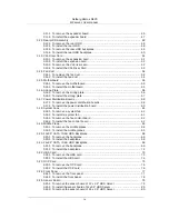
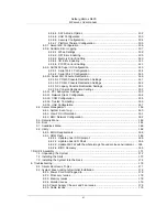
3.25.4. To install the sensor board of 24 x 2.5” HDD Server ................................... 81
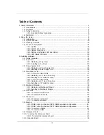
4. Connectors ...................................................................................................................... 82
4.1. Motherboard Connectors ........................................................................................ 83
4.1.1. 12 x 3.5” HDD Backplane Connectors ......................................................... 86
4.1.2. 24 x 2.5” HDD Backplane Connectors ......................................................... 87
4.2. Bridge Board Connectors ....................................................................................... 89
4.3. Middle Plane Connectors ....................................................................................... 90
4.3.1. Upper Middle Plane Connectors .................................................................. 90
4.3.2. NIC Middle Plane Connectors ..................................................................... 90
4.3.3. NTB Middle Plane ...................................................................................... 91
4.4. Power Distribution Board Connectors ..................................................................... 92
4.5. Rear HDD Backplane Connectors .......................................................................... 93
4.6. Expander Board Connectors .................................................................................. 94
4.7. Fan Control Board Connectors ............................................................................... 95
4.8. Interposer Board Connectors ................................................................................. 96
4.9. Sensor Board Connectors ...................................................................................... 97
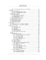
5. Cable Routing .................................................................................................................. 98
5.1. Cable Routing for 12 x 3.5” Hard Drives Configuration ............................................. 99
5.2. Cable Routing for 24 x 2.5” Hard Drives Configuration ........................................... 100
6. BIOS .............................................................................................................................. 101
6.1. BIOS Setup Utility ............................................................................................... 102
6.1.1. Entering BIOS Setup ................................................................................. 102
6.1.2. Main features ........................................................................................... 102
6.1.3. Setup Page .............................................................................................. 102
6.1.4. Keyboard Commands ................................................................................ 103
6.1.5. Menu Selection Bar .................................................................................. 105
6.1.6. Server Platform Setup Utility Screens ........................................................ 105
6.2. Main ................................................................................................................... 106
6.3. Advanced Screen ................................................................................................ 107
6.3.1. Processor Configuration ............................................................................ 108
6.3.1.1. Advanced Power Management Configuration ................................... 110
6.3.1.2. CPU P State Control ...................................................................... 111
6.3.1.3. CPU C State Control ...................................................................... 112
6.3.1.4. CPU T State Control ...................................................................... 113
6.3.1.5. CPU Advanced PM Tuning ............................................................. 114
6.3.1.6. Energy Perf BIAS ........................................................................... 115
6.3.2. QPI Configuration ..................................................................................... 116
6.3.3. Memory Configuration ............................................................................... 117
6.3.4. Memory Thermal ....................................................................................... 119
6.3.4.1. Memory Power Savings Advanced Options ...................................... 120
6.3.4.2. Memory RAS Configuration ............................................................ 121
6.3.5. IIO Configuration ....................................................................................... 122
6.3.5.1. IIO0 Configuration .......................................................................... 123
6.3.5.2. Socket 0 PcieD00F0-Port0/DMI ...................................................... 124
6.3.5.3. IIO1 Configuration .......................................................................... 125
6.3.5.4. IOAT Configuration ........................................................................ 126
6.3.5.5. Intel VT for Directed I/O (VT-d) ....................................................... 127
6.3.6. PCH Configuration .................................................................................... 128
6.3.6.1. PCI Express Configuration .............................................................. 129
6.3.6.2. PCI Express Root Port x ................................................................ 130
6.3.6.3. PCH SATA Configuration ............................................................... 131
Summary of Contents for Demos R420 M2
Page 1: ...Netberg Demos R420 M2 server User manual...
Page 2: ...Netberg Demos R420 M2 server User manual...
Page 12: ...1 Chapter 1 Safety Information...
Page 19: ...8 Chapter 2 About the Server...
Page 32: ...21 Chapter 3 Installing Hardware...
Page 93: ...82 Chapter 4 Connectors...
Page 95: ...Connectors 84 Figure 4 1 Mainboard Overview...
Page 108: ...Connectors 97 4 9 Sensor Board Connectors Figure 4 13 Sensor Board 1 I2C Connector...
Page 109: ...98 Chapter 5 Cable Routing...
Page 110: ...Cable Routing 99 5 1 Cable Routing for 12 x 3 5 Hard Drives Configuration...
Page 111: ...Cable Routing 100 5 2 Cable Routing for 24 x 2 5 Hard Drives Configuration...
Page 112: ...101 Chapter 6 BIOS...
Page 125: ...BIOS 114 6 3 1 5 CPU Advanced PM Tuning...
Page 172: ...BIOS 161 6 4 2 View FRU Information...
Page 176: ...BIOS 165 Menu Fields Settings Comments Network Device BBS Priorities 1...
Page 182: ...171 Chapter 7 Rail Kit Assembly...
Page 186: ...Rail Kit Assembly 175 Figure 7 3 Tightening the Thumbscrews...
Page 187: ...176 Chapter 8 Troubleshooting...


