viii
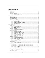
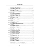
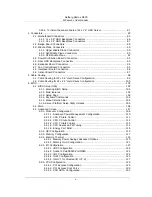
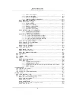
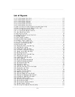
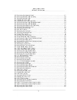
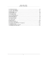
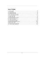
List of Figures
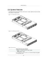
2.1. 3.5" HDD System Front View ......................................................................................... 10
2.2. 2.5" HDD System Front View ......................................................................................... 10
2.3. 3.5" HDD System Overview ........................................................................................... 14
2.4. 2.5" HDD System Overview ........................................................................................... 15
2.5. 3.5" HDD System Front View ......................................................................................... 16
2.6. 3.5" HDD System Front View ......................................................................................... 16
2.7. Back View with Two Nodes (with OCP 1G/10G Base-T NIC) ........................................... 17
2.8. Back View with Two Nodes (with OCP SFP+ NIC) .......................................................... 18
2.9. 3.5" Front Panel Buttons and LEDs ................................................................................ 19
2.10. 2.5" Front Panel Buttons and LEDs .............................................................................. 19
2.11. Rear Panel Power LEDs .............................................................................................. 19
3.1. Removing Top Cover .................................................................................................... 23
3.2. Sliding the Chassis Cover to the Front ........................................................................... 24
3.3. Installing Screws ........................................................................................................... 24
3.4. Power Supply Locations ................................................................................................ 25
3.5. Removing the Power Supply .......................................................................................... 26
3.6. Installing a Power Supply Unit ....................................................................................... 26
3.7. 3.5” SATA / SAS HDD Locations ................................................................................... 27
3.8. Sliding out the HDD Assembly ....................................................................................... 27
3.9. Removing the HDD ....................................................................................................... 28
3.10. Placing the HDD to the HDD Tray ................................................................................ 28
3.11. Fastening the Screws .................................................................................................. 29
3.12. Installing the HDD Assembly ........................................................................................ 29
3.13. 2.5” SATA / SAS HDD Locations .................................................................................. 30
3.14. Sliding out the HDD Assembly ..................................................................................... 30
3.15. Removing the HDD ..................................................................................................... 31
3.16. Placing the HDD to the HDD Tray ................................................................................ 31
3.17. Fastening the Screws .................................................................................................. 31
3.18. Installing the HDD Assembly ........................................................................................ 32
3.19. Node Locations ........................................................................................................... 33
3.20. Removing a Mainboard Module .................................................................................... 33
3.21. Installing a Mainboard Module ...................................................................................... 34
3.22. Removing the Heat Sink .............................................................................................. 35
3.23. Processor Location ...................................................................................................... 36
3.24. Opening the Load Plate ............................................................................................... 36
3.25. Lifting the Processor out of the Socket ......................................................................... 37
3.26. Closing the Load Plate ................................................................................................ 37
3.27. Placing the Processor .................................................................................................. 38
3.28. Location of System Memory ......................................................................................... 39
3.29. DIMM Socket Location ................................................................................................. 39
3.30. Lifting the DIMM out of the Socket ............................................................................... 41
3.31. Pressing the Retaining Clips Outward ........................................................................... 41
3.32. Inserting the DIMM into the Socket .............................................................................. 42
3.33. Interposer Board Location ............................................................................................ 43
3.34. Removing the interposer Board 1 ................................................................................. 44
3.35. Removing the Bracket ................................................................................................. 44
3.36. Removing the interposer Board 2 ................................................................................. 45
3.37. Expander Board Location ............................................................................................. 46
3.38. Removing the Expander Board Assembly ..................................................................... 46
Summary of Contents for Demos R420 M2
Page 1: ...Netberg Demos R420 M2 server User manual...
Page 2: ...Netberg Demos R420 M2 server User manual...
Page 12: ...1 Chapter 1 Safety Information...
Page 19: ...8 Chapter 2 About the Server...
Page 32: ...21 Chapter 3 Installing Hardware...
Page 93: ...82 Chapter 4 Connectors...
Page 95: ...Connectors 84 Figure 4 1 Mainboard Overview...
Page 108: ...Connectors 97 4 9 Sensor Board Connectors Figure 4 13 Sensor Board 1 I2C Connector...
Page 109: ...98 Chapter 5 Cable Routing...
Page 110: ...Cable Routing 99 5 1 Cable Routing for 12 x 3 5 Hard Drives Configuration...
Page 111: ...Cable Routing 100 5 2 Cable Routing for 24 x 2 5 Hard Drives Configuration...
Page 112: ...101 Chapter 6 BIOS...
Page 125: ...BIOS 114 6 3 1 5 CPU Advanced PM Tuning...
Page 172: ...BIOS 161 6 4 2 View FRU Information...
Page 176: ...BIOS 165 Menu Fields Settings Comments Network Device BBS Priorities 1...
Page 182: ...171 Chapter 7 Rail Kit Assembly...
Page 186: ...Rail Kit Assembly 175 Figure 7 3 Tightening the Thumbscrews...
Page 187: ...176 Chapter 8 Troubleshooting...


