background image


M-FS508NA-0
May 1997


NETGEAR


, Inc.

A Bay Networks Company
48015 Warm Springs Blvd.
Fremont, CA 94539 
USA


Installation Guide for 
the Model FS508 Fast
Ethernet Switch


FS508.BK  Page i  Wednesday, May 7, 1997  10:29 AM

Summary of Contents for FS508 - Switch

Page 1: ...S508NA 0 May 1997 NETGEAR Inc A Bay Networks Company 48015 Warm Springs Blvd Fremont CA 94539 USA Installation Guide for the Model FS508 Fast Ethernet Switch FS508 BK Page i Wednesday May 7 1997 10 29...

Page 2: ...o radio communications Operation of this equipment in a residential area is likely to cause harmful interference in which case users will be required to take whatever measures may be necessary to corr...

Page 3: ...V receivers Customer Support For assistance with installing and configuring your NETGEAR system or with post installation questions or problems contact your point of purchase representative To contact...

Page 4: ...iv FS508 BK Page iv Wednesday May 7 1997 10 29 AM...

Page 5: ...Physical Description Front Panel 2 1 Fast Ethernet Ports 2 2 Normal Uplink Push Button 2 2 LEDs 2 3 Rear Panel 2 4 FDX AUTO Duplex Toggle Switches 2 4 Chapter 3 Applications Desktop Switching 3 2 Seg...

Page 6: ...X AUTO Duplex Toggle Switches 5 1 Installation 5 2 Cabling 5 2 Network Adapter Cards 5 2 Configuration 5 2 Switch Integrity 5 2 Appendix A Technical Specifications General Specifications A 1 Appendix...

Page 7: ...ng the Model FS508 switch for network extension 3 4 Figure 3 4 Bridging 10 Mbps networks to 100 Mbps networks 3 5 Figure 3 5 High bandwidth file server connection 3 6 Figure 4 1 Attaching mounting bra...

Page 8: ...Tables Table 2 1 LED descriptions 2 3 Table B 1 RJ 45 plug and vista RJ 45 connector pin assignments B 2 Table C 1 Electrical requirements of Category 5 cable C 2 FS508 BK Page viii Wednesday May 7 19...

Page 9: ...network bandwidth or network capacity of 10 Mbps 100 Mbps or other amounts of network bandwidth For example with a total of 10 users the average bandwidth available to each user on a 10 Mbps network i...

Page 10: ...h in contrast is designed to support an entire workgroup on each port with each port having significant memory buffering and supporting thousands of MAC addresses Switches can also be classified by sp...

Page 11: ...For an illustration of using the switch to extend a network refer to Figure 3 3 on page 3 4 Because the Model FS508 switch is an ISO media access control MAC layer device the switch is network protoc...

Page 12: ...are to configure which saves time and minimizes the potential for configuration errors Normal Uplink push button to simplify network extension The switch can be connected to a hub using a simple strai...

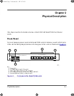
Page 13: ...witch as illustrated in Figure 2 1 Key 1 Power LED 2 100 Mbps LEDs for ports 1 through 8 3 Rx Tx and Collision LEDs for ports 1 through 8 4 10 100 Mbps ports with Link and FDX LEDs on each port 5 Norm...

Page 14: ...ction to the port is valid and that the port is operating in full duplex mode For further information about the vista RJ 45 connector and the RJ 45 connector refer to Appendix B Connector Pin Assignme...

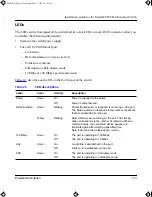
Page 15: ...ff Power is disconnected Rx Tx Collision Green Blinking Packet transmission or reception is occurring on the port The blinking action corresponds to the number of packets that are transmitted or recei...

Page 16: ...tomatically In this mode the 10 100 Mbps port operates in either full or half duplex mode depending on the operating mode of the remote port If the remote port cannot provide the proper signal to indi...

Page 17: ...ions Each switch can be used as a standalone device or can be used with 10 Mbps or 100 Mbps hubs or other interconnection devices in various configurations The configuration examples in this chapter i...

Page 18: ...y 1 Server with 100 Mbps connection 2 Model FS508 Fast Ethernet switch Normal Uplink push button set to Normal position 3 PCs with 100 Mbps Ethernet adapter cards installed 4 PC with 10 Mbps connectio...

Page 19: ...508 and Model FE516 Fast Ethernet hubs Key 1 NETGEAR Model FS508 Fast Ethernet switch Normal Uplink push button set to Normal position 2 100 Mbps connection 3 Model FE508 Fast Ethernet hub Normal Upli...

Page 20: ...tion of each switch Figure 3 3 illustrates a network of FE508 Fast Ethernet hubs integrated with three NETGEAR Model FS508 Fast Ethernet switches Key 1 Model FS508 Fast Ethernet switch Normal Uplink p...

Page 21: ...8 Fast Ethernet switch integrated with the NETGEAR Model EN516 Ethernet hub and the NETGEAR Model FE516 Fast Ethernet hub Key 1 Model FS508 Fast Ethernet switch Both Normal Uplink push buttons set to...

Page 22: ...es to be available to more users Figure 3 5 illustrates the NETGEAR Model FS508 Fast Ethernet switch integrated with two NETGEAR Model FE108 Fast Ethernet hubs A full duplex configurable adapter card...

Page 23: ...ts of the switch as described in Appendix A Technical Specifications Package Contents Unpack the contents of the package and verify them against the following list Model FS508 switch Self adhesive rub...

Page 24: ...d to Installing the Switch on a Flat Surface or Installing the Switch in a Rack Installing the Switch on a Flat Surface To install the switch on a desktop or any other flat surface follow these steps...

Page 25: ...stall the switch in a rack follow these steps 1 Attach the mounting brackets to the sides of the switch as illustrated in Figure 4 1 Hold a mounting bracket against each side of the switch and align t...

Page 26: ...over twisted pair cable when connecting similarly wired devices If you are connecting through port 8 set the Normal Uplink push button using the following guidelines to configure port 8 Set the Normal...

Page 27: ...ort cannot autonegotiate the 10 100 Mbps port will default to half duplex The factory setting of the duplex toggle switches is AUTO Move the toggle switch into the up position to FDX for full duplex m...

Page 28: ...FS508 BK Page 6 Wednesday May 7 1997 10 29 AM...

Page 29: ...d Appendix C Cabling Guidelines for additional information on crossover twisted pair or straight through cable use Verify that all other system components are functioning properly If any component fai...

Page 30: ...t may have been accidentally disconnected Network Adapter Cards Make sure the network adapter cards installed in the PCs are in working condition Configuration If problems occur after altering the net...

Page 31: ...IEEE 802 3I 10BASE T IEEE 802 3u 100BASE TX Data Rate 10 Mbps differential Manchester encoded IEEE 802 3 100 Mbps with 4B5B encoding and MLT 3 physical interface for 100BASE TX Interface RJ 45 connect...

Page 32: ...Operating altitude 10 000 ft 3 000 m maximum Storage altitude 10 000 ft 3 000 m maximum Electromagnetic Emissions Meets requirements of CE mark commercial FCC Part 15 Subpart B Class A EN 55 022 CISPR...

Page 33: ...bps port Frame forward rate 14 800 frames second maximum on 10 Mbps port 148 000 frames second maximum on 100 Mbps port Forwarding modes Cut through fragment free cut through store and forward Network...

Page 34: ...FS508 BK Page 4 Wednesday May 7 1997 10 29 AM...

Page 35: ...5 plugs The RJ 45 plug accepts 4 pair unshielded twisted pair UTP or shielded twisted pair STP 100 cable and connects into the vista RJ 45 connector The vista RJ 45 connector also referred to as a 10...

Page 36: ...able 5 1 RJ 45 plug and vista RJ 45 connector pin assignments Pin Normal assignment Uplink assignment 1 Input Receive Data Output Transmit Data 2 Input Receive Data Output Transmit Data 3 Output Trans...

Page 37: ...z bandwidth 100BASE TX operation uses one pair of wires for transmission and the other pair for receiving and for collision detection When installing Category 5 UTP cabling use the following guideline...

Page 38: ...The patch panel and other connecting hardware must meet the requirements for 100 Mbps operation Category 5 Only 0 5 inch 1 5 cm of untwist in the wire pair is allowed at any termination point Cable S...

Page 39: ...Most repeaters and switch ports are configured as media dependent interfaces with built in crossover ports called MDI X or normal ports Figure 5 1 illustrates straight through twisted pair cable Key A...

Page 40: ...tribution cable rating To wire patch panels you need two Category 5 UTP cables with an RJ 45 plug at each end as shown in Figure 5 3 Key 1 RJ 45 plug 2 Category 5 UTP patch cable Figure 5 3 Category 5...

Page 41: ...2 specifications C 2 straight through twisted pair 4 4 5 1 C 3 termination method C 1 troubleshooting 5 2 Collision LED 2 1 2 3 connections to other devices 4 4 crossover twisted pair cable 4 4 5 1 C...

Page 42: ...5 connector RJ 45 plug pin assignments B 1 using for patch cables C 4 using with UTP cable 2 2 Rx Tx LED 2 3 S segment switching 1 2 3 3 server connections 3 6 site preparation 4 1 straight through tw...

Reviews: