Reference Manual for the ProSafe Wireless 802.11g Firewall/Print Server Model FWG114P
Introduction
2-7
March 2004, 202-10027-01
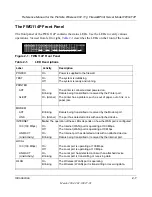
The FWG114P Front Panel
The front panel of the FWG114P contains the status LEDs. Use the LEDs to verify various
operations. Viewed from left to right,
Table 2-1
describes the LEDs on the front of the router.
Figure 2-1: FWG114P Front Panel
Table 2-1.
LED Descriptions
Label
Activity
Description
POWER
On
Power is supplied to the firewall.
TEST
On
Off
The system is initializing.
The system is ready and running.
PRINTER
ACT
On
Blinking
The printer is connected and powered on.
Data is being transmitted or received by the Printer port.
ALERT
On (Amber)
The printer has a problem, such as out of paper, out of ink, or a
paper jam.
MODEM
ACT
Blinking
Data is being transmitted or received by the Modem port.
LINK
On (Amber)
The port has detected a link with an attached device.
INTERNET
Note:
The operation of these LEDs depends on how the WAN port is configured.
100 (100 Mbps)
On
Off
The Internet (WAN) port is operating at 100 Mbps.
The Internet (WAN) port is operating at 10 Mbps.
LINK/ACT
(Link/Activity)
On
Blinking
The Internet port has detected a link with an attached device.
Data is being transmitted or received by the Internet port.
LOCAL
100 (100 Mbps)
On
Off
The Local port is operating at 100 Mbps.
The Local port is operating at 10 Mbps.
LINK/ACT
(Link/Activity)
On
Blinking
The Local port has detected a link with an attached device.
The Local port is transmitting or receiving data.
WLAN On
Blinking
The Wireless (WLAN) port is operating.
The Wireless (WLAN) port is transmitting or receiving data.
ProSafe 802.11g Wireless Firewall/Print Server
Broadband
MODEL
FWG114P
PWR
P R I N TER
M O D EM
I N TER N ET
LO CA L
W LA N
TEST
ACT
ALERT
ACT
LINK
100
1
2
3
4
LNK/ACT
100
LNK/ACT

