ProSecure Web/Email Security Threat Management (STM) Appliance Reference Manual
Introduction
1-15
v1.0, September 2009
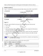
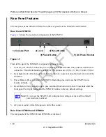
Figure 1-6
shows the rear panel components of the STM300 and STM600.
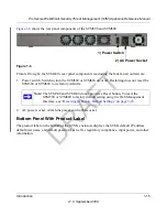
From left to right, the STM600’s rear panel components (excluding the four fan air outlets) are:
1. Power switch. Switch to turn the STM300 or STM600 on or off. Restarting does not reset the
STM300 or STM600 to its factory defaults.
2. AC power socket. Attach the power cord to this socket.
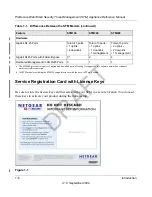
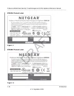
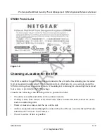
Bottom Panel With Product Label
The product label on the bottom of the STM’s enclosure displays the STM’s default IP address,
default user name, and default password, as well as regulatory compliance, input power, and other
information.
Figure 1-6
Note:
The STM300 and STM600 do not provide a Reset button. To reset the
STM300 or STM600 to factory default setting using the Web Management
Interface, see
“Reverting to Factory Default Settings” on page 3-18
.
1) Power Switch
2) AC Power Socket
DRAFT

