- ENGLISH -
- 65 -
I
NSTALLATION OF
N
ET
M
AN
101
PLUS
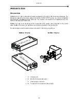
1. Remove the protection strip of the backup battery.
2.
Connect the “UPS SERIAL” port of the device to the serial port of the inverter using the
cable supplied.
3. Connect the device to the network by means of connector RJ-45 (see
“Specifications for
the cabling of the network cabl
e”)
4. Connect the power supply unit to the device.
I
NSTALLATION OF
N
ET
M
AN
102
PLUS
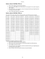
The jumper JP1
2 must be closed for the following inverter: see “P/N” field on the rating label
HGT1151ARU
HGT1151ARU-E
HGT1151ARU-D
6PHV10K2A
6PHV10K2A-D
6PHV10K2A-INE
6PHV10K2A-IF7
HGT1151BRU
HGT1151BRU-E
HGT1151BRU-D
6PHV1K51A
6PHV1K51A-D
6PHV1K51B-INE
6PHV1K51B-IF7
HGT1201ARU
HGT1201ARU-E
HGT1201ARU-D
6PHV1K51B
6PHV1K51B-D
6PHV2K01B-INE
6PHV2K01B-IF7
HGT1201BRU
HGT1201BRU-E
HGT1201BRU-D
6PHV2K01A
6PHV2K01A-D
6PHV2K81B-INE
6PHV2K81B-IF7
HGT1281ARU
HGT1281ARU-E
HGT1281ARU-D
6PHV2K01B
6PHV2K01B-D
6PHV3K11A-INE
6PHV3K11A-IF7
HGT1281BRU
HGT1281BRU-E
HGT1281BRU-D
6PHV2K81A
6PHV2K81A-D
6PHV4K01B-INE
6PHV4K01B-IF7
HGT1311ARU
HGT1311ARU-E
HGT1311ARU-D
6PHV2K81B
6PHV2K81B-D
6PHV4K02B-INE
6PHV4K02B-IF7
HGT1401ARU
HGT1401ARU-E
HGT1401ARU-D
6PHV3K11A
6PHV3K11A-D
6PHV4K62A-INE
6PHV4K62A-IF7
HGT1401BRU
HGT1401BRU-E
HGT1401BRU-D
6PHV4K01A
6PHV4K01A-D
6PHV6K03A-INE
6PHV6K03A-IF7
HGT1402ARU
HGT1402ARU-E
HGT1402ARU-D
6PHV4K01B
6PHV4K01B-D
6PHV10K2XA-INE
6PHV10K2XA-F7
HGT1402BRU
HGT1402BRU-E
HGT1402BRU-D
6PHV4K02A
6PHV4K02A-D
6PHV1K51XA-INE
6PHV1K51XA-F7
HGT1462ARU
HGT1601ARU-E
HGT1601ARU-D
6PHV4K02B
6PHV4K02B-D
6PHV2K01XA-INE
6PHV2K01XA-F7
HGT1602ARU
HGT1601BRU-E
HGT1601BRU-D
6PHV4K62A
6PHV6K02A-D
6PHV2K81XA-INE
6PHV2K81XA-F7
HGT3102ARU
HGT1602ARU-E
HGT3102ARU-D
6PHV6K03A
6PHV6K02B-D
6PHV3K11XA-INE
6PHV3K11XA-F7
HGT1151RUXA
HGT3102ARU-E
6PHV10K2XA
6PHV6K03A-D
6PHV4K01XA-INE
6PHV4K01XA-F7
HGT1201RUXA
6PHV1K51XA
6PHV4K02XA-INE
6PHV4K02XA-F7
HGT1281RUXA
6PHV2K01XA
6PHV4K62XA-INE
6PHV4K62XA-F7
HGT1311RUXA
6PHV2K81XA
6PHV6K03XA-INE
6PHV6K03XA-F7
HGT1401RUXA
6PHV3K11XA
HGT1402RUXA
6PHV4K01XA
HGT1462RUXA
6PHV4K02XA
HGT1602RUXA
6PHV4K62XA
HGT3102RUXA
6PHV6K03XA
Complete the installation proceeding as follows:
1. Remove the protection strip of the backup battery.
2. Remove the cover of the UPS expansion slot by removing the two retaining screws.
3. Insert
NetMan 102 plus
in the slot.
4. Connect the device to the network by means of connector RJ-45 (see
“Specifications for
the cabling of the network cable
”)
5. Secure
Netman
in the slot using the two screws removed previously.


