51
SitePlayer Telnet User’s Manual
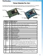
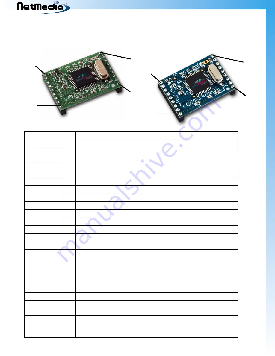
Telnet Module Pin-Out
The SitePlayer Telnet module consists of a circuit board with a dual-row 18-pin header. Pin 1 is identified
with a white dot. The RoHS version of the module is blue, while the non-RoHS version is green
Pin Name
I/O Description
1
LINK*
O Link Status
2
3
TPin+
TPin-
I
Twisted Pair input. Receives 10 Mbits/s differential Manchester
encoded data from the 10BaseT transformer.
4
5
TPout-
TPout+
O Twisted Pair output. Transmits 10 Mbits/s differential Manchester
encoded data to the 10BaseT transformer.
6
GND
-
Device ground.
7
RxD
I
Receive serial data.
8
TxD
O Transmit serial data.
9
Vcc
-
Device 5V power.
10 RST
I
Hardware reset.
11 RI
I
Ring indicator.
12 DCD
I
Data Carrier Detect.
13 DSR
I
Data Set Ready.
14 RTS
O Request to send. Used for hardware flow control.
15 DTR
FDRST
O
I
Data Terminal Ready.
Factory default reset. Resets device to factory defaults. Hold pin
to ground before applying power or RST. Allow to float once
power is applied. Factory default reset will take approximately
15 seconds to complete during which time power should not be
removed.
16 CTS
I
Clear to Send. Used for hardware flow control.
17 LED
O Status LED. Used to indicate online-status and reflashing status.
Can also be user controlled.
18 Lsense*
I
Senses status of LINK* signal. This
must
be connected to pin 1
LINK*. SitePlayer uses this to determine if cable is plugged in and
for other network functions.
Pin 9
Pin 1
Pin 10
Pin 18
Pin 9
Pin 1
Pin 10
Pin 18
RoHS
Summary of Contents for SitePlayer Telnet Series
Page 50: ...SitePlayer Telnet User s Manual 50 Telnet Carrier Schematic ...
Page 52: ......

