


[ENG] NetPing 2 IP PDU ETH 53R14 & NetPing 2 IP PDU GSM3G 203R15, User guide -[ENG][2PWR] Connecting External Sensors
and Accessories
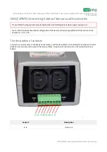
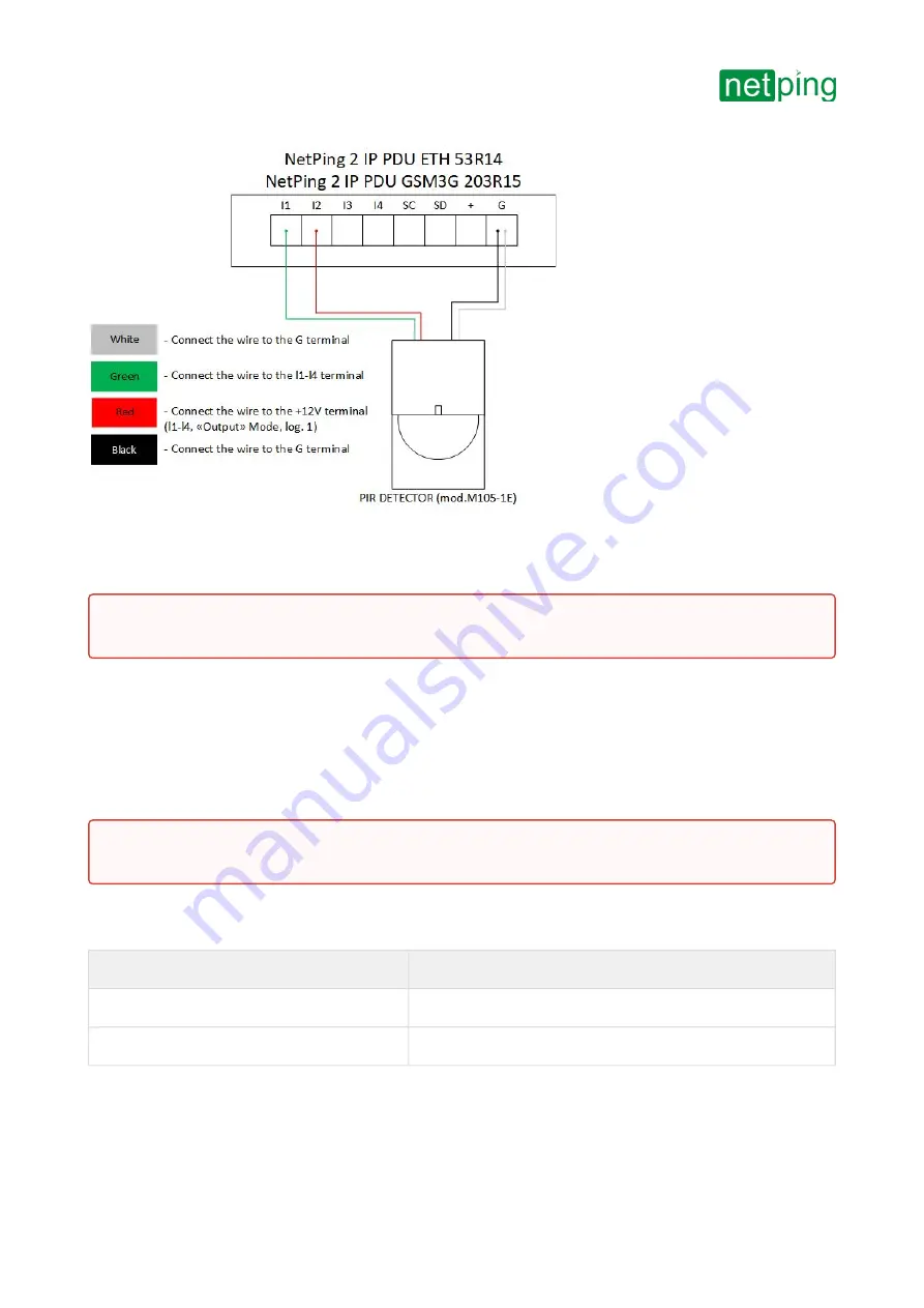
[ENG][2PWR] Connecting External Sensors and Accessories
–
Actuation Devices
The number of actuation devices is limited by free IO lines of the device and the total current consumption of
devices in active mode.
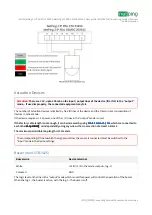
If the device re12 V power, one of the I / O lines in the “output” mode is used.
Buzzer wire
Device terminal
White
+12
В
(I1-I4 in the mode
«output», log. 1)
Coloured
GND
The logic level on the line in the “output” mode which is used for power will control the operation of the buzzer.
When the log.1 - the buzzer is active, with the log. 0 - the buzzer is off.
Attention!
There are 12 V, up to 200 mA
on the input / output lines of the device (IO1-IO4) in the “output”
mode, . If used improperly, the connected equipment may fail.
If the factory cable length is not enough, it can be increased by using
, which are connected to
each other
, or independently using any wire with a cross section of at least 0.4 mm2.
sequentially
sequentially
sequentially
sequentially
If the factory cable length is not enough, it can be increased by using
, which are connected to
each other
, or independently using any wire with a cross section of at least 0.4 mm2.
sequentially
sequentially
sequentially
sequentially
The maximum permissible loop length is 100 meters.
The maximum permissible loop length is 100 meters.
The corresponding IO line to which the signal wire from the sensor is connected must be switched to the
“input” mode in the device settings.


