background image


[ENG] UniPing server solution v4/SMS & UniPing 

server solution v3, User guide


Summary of Contents for Uniping server solution v3/SMS

Page 1: ... ENG UniPing server solution v4 SMS UniPing server solution v3 User guide ...

Page 2: ... 9 Removing a SIM Card 9 USS Sockets and Indication Elements 10 POWER LED 10 IO Lines Connection Terminals 10 IO STATE LEDs 11 Thermo IR Terminals 11 Smoke Terminals 12 1W Sockets 12 RS232 RS485 Sockets 13 Relay Socket PWR 15 LAN Sockets 16 GSM Sockets 17 Reset Button 17 Power Supply Inputs 17 USS Using IO Lines to Control External Devices in the Output Mode 19 Electric parameters of IO lines 19 E...

Page 3: ...External Sockets 28 Electricity Meter Energy Meter CE102 29 Buzzer mod STD 3025 29 USS Setting Parameters to Default Values to the Factory Settings 30 USS Shipping Kit 31 Shipping kit of a UniPing server solution v3 SMS device 31 Shipping kit of a UniPing server solution v3 device 32 USS Warranty 33 USS Operating and Storage Conditions 34 USS Safety Precautions 35 USS Where to Get a Document of a ...

Page 4: ... ENG UniPing server solution v4 SMS UniPing server solution v3 User guide ...

Page 5: ...device for an operation A User Guide is designed for network administrators and users who set up or operate a device To work with a device properly a user must have an idea about the principles of building and functioning of local networks as well as possess the next knowledge and skills Basic knowledge in the area of local and global networks Basic knowledge in the area of architecture and princi...

Page 6: ...does not correspond to expectations of a user and his her opinion about where and how to use all the above All copyrights on supplied devices described in this User Guide as well as firmware and software of devices and this User Guide belong to NetPing global Ltd Сopying replication and translation of this user guide to other languages are not allowed without a prior written permission of a righth...

Page 7: ...s notifying about events in a server room through SNMP TRAP SYSLOG e mail and SMS for a UniPing server solution v3 SMS device with a built in GSM modem building a system of sound and light alerting using a siren alarm АS 10 light beacons and other indication elements A monitoring device allows connecting a large number of various sensors Readings of sensors may be taken through SNMP HTTP protocols...

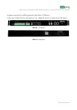
Page 8: ... v3 User guide USS A Device Overview USS A Device Overview Appearance of a UniPing server solution v3 Device A device has a standard size to be mounted in a 19 rack A height of a device is 1U Appearance is shown below Picture 3 Front panel Picture 4 Back panel ...

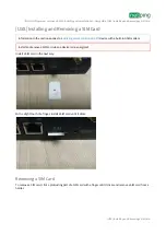
Page 9: ... SIM card in the next way With a slight touch of a finger install a SIM card until it clicks Removing a SIM Card To remove a SIM card click a protruding part of a SIM card with a finger until it clicks and remove a SIM card from a holder Information in the section applies to a UniPing server solution v3 SMS device with a built in GSM modem Install and remove a SIM card when a device is de energize...

Page 10: ... DISCRETE IO terminal block is used to connect universal IO lines There are eight IO lines in a block For each line there are two contacts IO and GND To make connecting sensors convenient there are terminals 5 V and 12 V in a DISCRETE IO block A maximum summed current on 5V and 12V terminals is 200mA it is limited by a self resetting fuse To recover a terminal operation after a reboot there is a n...

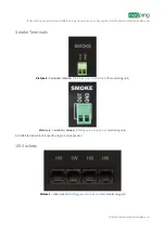
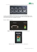
Page 11: ...ration that their summed maximum triggering current should not exceed 200mA IO STATE LEDs IO STATE LEDs see picture 1 and picture 2 signal about a status of the first four IO lines When a LED is turned on a corresponding IO line is in a status logic 1 and a turned off LED means a logic status 0 Thermo IR Terminals Picture 3 Terminals Thermo IR UniPing server solution v4 SMS monitoring unit Picture...

Page 12: ...ts and Indication Elements Smoke Terminals Picture 5 Terminals Smoke UniPing server solution v4 SMS monitoring unit Picture 6 Terminals Smoke UniPing server solution v3 monitoring unit A SMOKE terminal block is used to plug in a smoke sensor 1W Sockets Picture 7 1W sockets UniPing server solution v4 SMS monitoring unit ...

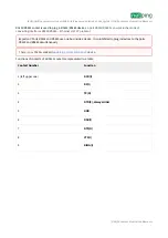
Page 13: ...o plug in sensors of a model line 1 Wire that are built using a 1Wire technology To make sensors plug in more convenient there are four sockets on a body of a device It is possible to plug in more than four sensors of a model line 1 Wire using splitters and extenders RS232 RS485 Sockets Picture 9 RS232 RS485 sockets UniPing server solution v4 SMS monitoring unit Picture 10 RS485 sockets UniPing se...

Page 14: ...onverting interfaces RS232 RS485 Ethernet via TCP protocol Functions of contacts of a RS232 socket are represented in a table Contact Number Function 1 left upper one DCD I 2 RX I 3 TX O 4 DTR 0 always HIGH 5 GND 6 DSR I 7 RTS O 8 CTS I 9 RING I Important Ports RS232 and RS485 use one bus inside a device It is prohibited to plug in devices to the ports RS232 and RS485 simultaneously There is no RS...

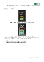
Page 15: ...ocket PWR UniPing server solution v3 monitoring unit Contacts of a relay built into a body of a device are output normally opened and normally closed A relay can be used for managing a Reset button of a computer as well as for connecting an Alarm АС 10 Electrical parameters of power management channel RELAY are as follows The maximum permissible voltage on the relay contacts is 50V The maximum all...

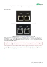
Page 16: ...itional equipment another NetPing device an administrator s laptop etc which gives a possibility not to install an additional switch on a remote land These ports are equal and any of them can be used to connect to a network Ethernet ports have two LEDs The left one is CPU and when it is lighting it means a device is turned on It blinks when packages are transferred to a network The right one is Li...

Page 17: ...esetting parameters to default values To reset the parameters press a Reset button with a sharp object and hold it during a device is turning on Power Supply Inputs There are two power inputs on the rear panel The first one pictures 16 17 is used to power the device from an external 5V DC power supply not less than 1 5 A The power supply must have a galvanic barrier with a 220V network The other p...

Page 18: ...USS Sockets and Indication Elements Picture 16 5V DC Input UniPing server solution v4 SMS monitoring unit Picture 17 5V DC Input UniPing server solution v3 monitoring unit Picture 18 220V AC Input UniPing server solution v4 SMS monitoring unit Picture 19 220V AC Input UniPing server solution v3 monitoring unit ...

Page 19: ...mp heating boiler heaters etc Remote management of a power installation diesel generator gasoline It is acceptable to use intermediate relays with a power supply voltage of 12 V from an external source A ready socket can be used for IO lines connection NetPing AC DIN socket In addition we can advise ready assembly relays of other manufacturers which can be connected to our devices BM8070D a power ...

Page 20: ...g server solution v4 SMS UniPing server solution v3 User guide USS Using IO Lines to Control External Devices in the Output Mode USS Using IO Lines to Control External Devices in the Output Mode Equivalent Сircuit ...

Page 21: ...nsor Flex UniPing server solution v4 SMS UniPing server solution v3 Terminal Block Yellow Labeled wire red SCL Green Second wire after a labeled one SDA Red Third wire after a labeled one 5V Black Fourth wire after a labeled one GND A sensor is shipped with an inseparable cable with connectors at the ends A cable length can be extended using RC 4 sensor cable extenders which are consequentially pl...

Page 22: ... cable extenders of RC 4 sensor which are sequentially plugged one into another Or it can be done independently with the help of any wire with a minimum cross section of 0 4 mm2 Maximum allowable length of a flat cable is 100 m Leakage Sensors model 2605 A leakage sensor is plugged by a four line wire according to the table Important Sensors of a dry contact type a supply voltage sensor a leakage ...

Page 23: ...ines 1 8 Second wire GND A sensor is packaged with an inseparable cable with connectors on the ends A cable length can be increased with the help of flat cable extenders of RC 4 sensor which are sequentially plugged one into another Or it can be done independently with the help of any wire with a minimum cross section of 0 4 mm2 Maximum allowable length of a flat cable is 100 m Glass Breakage Sens...

Page 24: ... section of 0 4 mm2 Maximum allowable length of a flat cable is 100 m Shock Sensors A shock sensor is plugged by a four line wire according to the table Sensor Flex UniPing server solution v4 SMS UniPing server solution v3 Terminal Block Blue wire One of IO lines 1 8 Green wire One of IO lines 1 8 Red wire 12V Black wire GND A shock sensor takes two IO lines You can plug no more than four such sen...

Page 25: ...e with connectors on the ends A cable length can be increased with the help of flat cable extenders of RC 4 sensor which are sequentially plugged one into another Or it can be done Important Sensors of a dry contact type a supply voltage sensor a leakage sensor and others are plugged to IO lines of a device You can plug up to eight sensors of this set Important A correspondent IO line should be se...

Page 26: ...nimum cross section of 0 4 mm2 Maximum allowable length of a flat cable is 100 m Smoke detector mod M206 5E A smoke sensor is plugged by a two line wire according to the table Sensor Flex Type 1 Sensor Flex Type 2 Sensor Flex Type 3 UniPing server solution v4 SMS UniPing server solution v3 Terminal Block Red Black Black Black GND Yellow Green Red Black Red OUT ...

Page 27: ...lly plugged one into another Or it can be done independently with the help of any wire with a minimum cross section of 0 4 mm2 Maximum allowable length of a flat cable is 100 m Theoretically a number of sensors in a circuit is not limited The main requirement is to maintain a loop resistance in a standby mode at 3 3 kOhm determined by a resistor at the end of a circuit I e sensors can be added to ...

Page 28: ...tact NC is a normally closed contact Sensor Flex UniPing server solution v4 SMS UniPing server solution v3 Terminal Block Red 5V Black GND Blue Green Middle contact of a Relay terminal 5V terminal is plugged to a normally opened relay contact a left terminal in Relay by an auxiliary wire A relay with normally closed contacts is used for a load commutation in a NetPing AC DIN This means having 220 ...

Page 29: ...NO is normally opened contact NC is normally closed contact with using 12V Loop Color UniPing server solution v4 SMS UniPing server solution v3 Terminal Block Black GND Red NO RELAY 12V Middle contact RELAY A sensor is packaged with an inseparable cable with connectors on the ends A cable length can be increased with the help of flat cable extenders of RC 4 sensor which are sequentially plugged on...

Page 30: ...IP and MAC addresses access filters a user name a password etc To reset parameters to default settings fulfill the next actions sequentially Turn off a power supply of a device Press the Reset button a button Set for a UniPing v3 monitoring unit Turn on a power supply of a device continuing to hold Reset button pressed for 15 20 seconds Release the button All parameters of a device are set to defa...

Page 31: ...hipping Kit Shipping kit of a UniPing server solution v3 SMS device A shipping kit includes UniPing server solution v3 SMS device 1 pc GSM antenna 1 pc computer power cable 1 8 meters 1 pc mounting ears 2 pcs fasteners for ears 4 pcs mating terminals 9 pcs screwdriver 1 pc zip bag 1 pc memo 1 pc packaging box 1 pc ...

Page 32: ...User guide USS Shipping Kit USS Shipping Kit Shipping kit of a UniPing server solution v3 device A shipping kit includes UniPing server solution v3 device 1 pc computer power cable 1 8 meters 1 pc mating terminals 9 pcs screwdriver 1 pc memo 1 pc packagng box 1 pc ...

Page 33: ... update for the customer Only the errors that block normal use of the device at conditions and for performing functions described in this User Guide are a subject to mandatory fix This warranty does not apply to cases when defects appear because of a misuse of a device any modifications of a device without a written permission of the manufacturer opening up a device a warranty sticker on the case ...

Page 34: ...without maintenance Highly developed functionality of remote setting and configuration of a device allows changing any parameters remotely and centrally for the most of the devices Devices should be stored in a temperature range between 40 С and 70 С In rooms for keeping a device a content of dust acid and alkali gases aggressive gases and other harmful impurities causing corrosion should not exce...

Page 35: ...d It is prohibited to open the case of a device Do not drop a device and avoid impact of force on it Protect a device from high humidity levels It is prohibited to touch a device and a connected equipment with wet hands Use devices only indoors Do not place a device at a surface or inside heating devices such as microwaves stoves and heaters Do not use a device in locations marked as potentially e...

Page 36: ...cording to the changes made to the firmware To find an actual version of Firmware Description on the manufacturer s web site there is a need to Go to the page of a description of a necessary device UniPing server solution v3 SMS UniPing server solution v3 Go to the section Documentation and Files Go to the link Firmware description DKSF 70 5 IU A version in the document Firmware Description must c...

Page 37: ... of using the devices and news on issuing new firmware versions If any problems arise when using a device or there is a need for additional information contact a technical support by the address support netpingdevice com Pages of devices on a manufacturer s website UniPing server solution v3 SMS UniPing server solution v3 Information about a functionality of a device and its configuration using a ...

Reviews: