

10
5-8. Configure Scene and Get Scene Configuration
Support “Configure Scene” and “Get Scene Configuration” functions and control up to four scenes each key
(
or
or
).
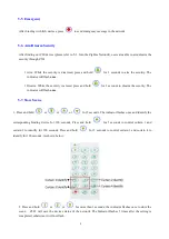
5-9. Recall Scene
Press Scenario
or
or
less than 3 seconds t
o recall scene. When configurating
more than once scene through “Configure Scene”, press
or
or
to switch saved
scenes.
5-10. Delete Stored Scene
Press and hold
for
3 seconds, and the indicator will flash
once
. After the scene is deleted,
the indicator flashes
7 times
;
otherwise, it
flashes
3 times
.
The scene cannot be restored after deleting.
It is recommended that users delete scene when first-time use or Z503 joins a new ZigBee network.
The enrolled CIE will be deleted when users delete stored scenes. Thereafter, users can press 2
nd
function key
and press
to enroll to CIE again.
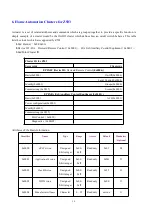
5-11. Sleeping Mode
Z503 is designed to go into sleeping mode for power-saving in some situations:
A. When it doesn’t find a network to join → Z503 will go to sleeping mode.
B. While the device is in the network → the sleeping period is 5 minutes; it will wake up every 5
minutes to keep online.
C. Once Z503 was joined to a network and by any chance the network is no longer existed or the device
is out of the network → Z503 will wake up every 15 minutes to find the network it joined before. It
never keeps in sleeping mode and continues to find its network every 15 minutes. This condition
would consume up to 30 times power spending compared to normal-operating status. To prevent this
unwanted power consumption, we recommend that users manually power off the device.


