Page 102/ 191
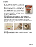
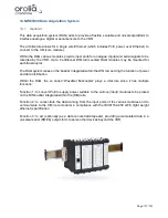
The HSS consists of two sub-assemblies. A deckmount sub-
assembly is directly fastened to the ship and provides watertight
cable entries for the single wire WaveNet connection.
Together with the deck mount a set of stainless-steel bolts are
provided to be used for bolting the deckmount on a suitable position
on deck.
A removable sub-assembly (the capsule) is attached to the mounting
base with a unique quick release mechanism for recovery by either a
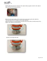
diver or ROV. To ensure water tightness between sub-assembly and
deckmount, a roll of vulcanized tape is delivered, which needs to be
attached underneath the quick release mechanism after connecting
the cable to CPU of the storage medium.
A)
Deckmount
Install the stainless-steel deck mount on a suitable place using the supplied bolts as per
regulatory requirement. (Freedom of access and retrieval, approx. 1-meter free space around).
B)
Cabling
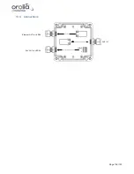
Lead the network cable through the gland at the side of the deck mount and ensure that
sufficient length is available (30 cm). The M16 gland is an EMC gland requiring that the shield of
the cable be exposed and connected within the gland on entry to the deck mount.
(Network cable is not standard supply)
C) Connector
Attach a suitable RJ-45 (preferably industrial type) connector to the network cable as connection
instruction provided with the connector.
(RJ45 connector can be purchased separately on request)
Summary of Contents for NW6000
Page 1: ......
Page 91: ...Page 91 191...
Page 92: ...Page 92 191...
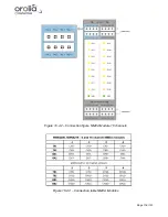
Page 120: ...Page 120 191 Figure 17 4 2 Connection figure Digital Module 16 channels...
Page 121: ...Page 121 191 Figure 17 4 3 Connection figure Digital Module 24 channels...
Page 125: ...Page 125 191 Figure 18 4 2 Connection figure Analogue Module 8 channels...
Page 126: ...Page 126 191 Figure 18 4 3 Connection figure Analogue Module 12 channels...
Page 184: ...Page 184 191 Figure 5 8 1 Sample dataset playback...


