Page 12/ 191
operation and maintenance Voyage data recorder NW6000-manual
’ above. The version indicated
in above amendment record is the version of this complete document.
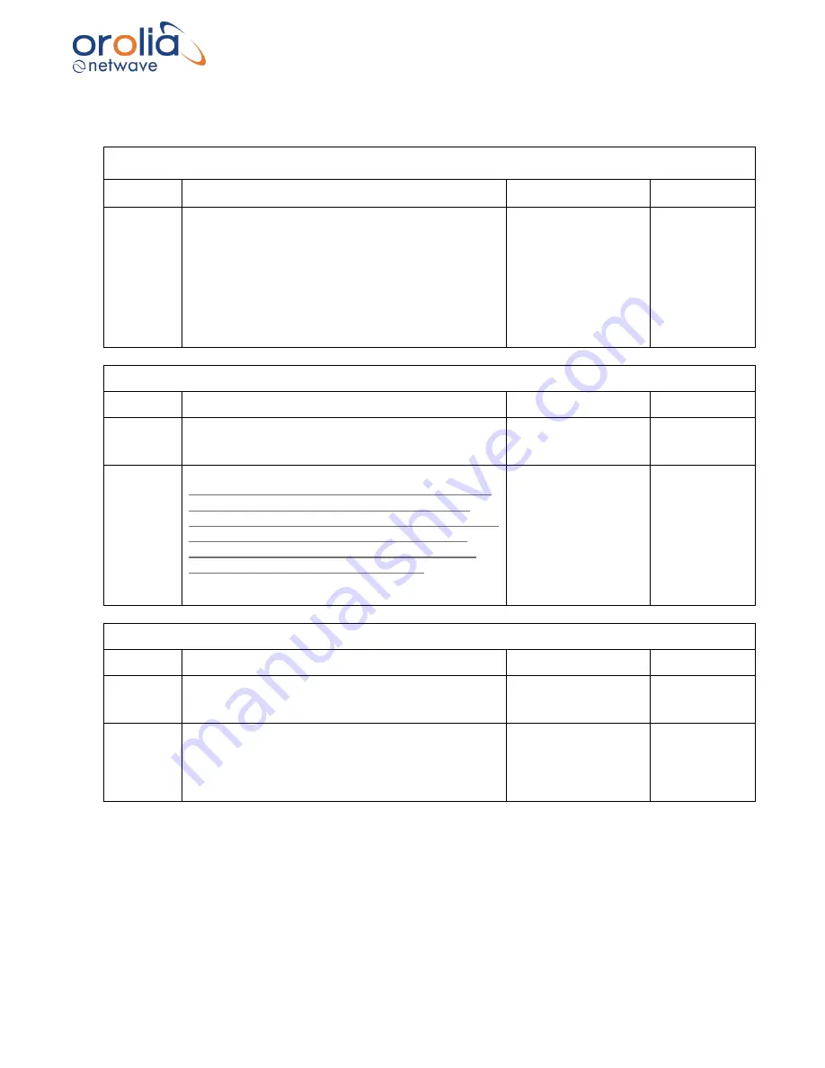
General part
(R
elated to ‘Installation manual’ and ‘Operator and maintenance manual’)
Version
Amendment reference
Date
Updated by
Instal.man
ual: 1.12
Operat.
And
maint.
Manual:
1.8
-
‘Installation manual’ and ‘Operator and
maintenance manual’ merged into one document
(reorganization of chapters). ‘General’ part is
related to both manuals.
-
‘Service request’ chapter added in General part.
- USB-card enclosed to hard copy manual with the
digital version of the manual, User Manual of the
TRON 40VDR and Playback Software.
14
th
of March 2017
C. van ‘t Riet
Installation manual
Version
Amendment reference
Date
Updated by
1.10
Addition in section 14 about new Docking Module
(83180 MkII): new wire scheme and new led
indication.
24
th
of August 2016
C. van ‘t Riet
1.11
- Declaration of Conformity enclosed (section 2.3).
- Clarifications for TRON 40VDR (Section 14): wire
scheme for new Docking Module MKII/Junction
Box, clarifications of grounding of Junction box, new
led indication on Docking module, more details
about mounting position, use of vulcanizing tape
added, settings of IP-address removed.
- Restart VDR added (section 24.7).
- Addition in section 24.2 about displayed ZDA time.
31
st
of October 2016
C. van ‘t Riet
Operator and maintenance manual
Version
Amendment reference
Date
Updated by
1.6
- Addition in section 8.6 about calculation recorded
time.
- Addition in section 14.2 about displayed ZDA time.
24
th
of February 2016
C. van ‘t Riet
1.7
- Clarification of Russian mark of conformity Annex
III.
-
‘Restart VDR’ section 14.8 added.
-
‘Led indication’ TRON 40VDR MKII section 11.2
added.
19
th
of October 2016
C. van ‘t Riet
Summary of Contents for NW6000
Page 1: ......
Page 91: ...Page 91 191...
Page 92: ...Page 92 191...
Page 120: ...Page 120 191 Figure 17 4 2 Connection figure Digital Module 16 channels...
Page 121: ...Page 121 191 Figure 17 4 3 Connection figure Digital Module 24 channels...
Page 125: ...Page 125 191 Figure 18 4 2 Connection figure Analogue Module 8 channels...
Page 126: ...Page 126 191 Figure 18 4 3 Connection figure Analogue Module 12 channels...
Page 184: ...Page 184 191 Figure 5 8 1 Sample dataset playback...


