Page 24/ 191
Part 1: Installation manual
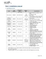
1. Specification sheet
Unit
Type
Number
Dimensions
(mm)
(H x D x W)
Weight
(kg)
Specifications
Core module
NW6000
484 x 450 x 45
16.5
(incl.
batteries)
-
PSU (110/230 Vac, 50/60 Hz) / 100
Watt
-
Includes mains filter
-
Built-in UPS
-
10 port switch (8 x PoE, 2 x Non-PoE)
-
CPU unit with min. 30 days storage
Bulkhead
mount frame
and cover
NW6900
744 x 464 x 115
11
(excl. core
module)
- Internal wiring
- External RJ45 connector bank
Bridge
Control Unit
NW6010
150 x 100 x 134
1.8
-
Powered from Core module thru PoE
-
4” touch color screen
-
Panel mounted with frame (IP20)
Microphone
(Internal &
External)
NW6030
70 x 83 x 83
0.4
-
Powered from Audio Hub
-
Analogue
-
LED identification light
Audio Hub
NW6031
35 x 152 x 106
0.35
-
Powered using PoE
-
Bulkhead mounted
VHF
Interface
NW6060
180 x 87 x 47
0.5
-
Powered using PoE
-
2 line-in
-
Interface for microphones
-
Bulkhead mounted (IP20)
Hardened
FRM
NW6860
411 x 311
27.5
-
Powered thru PoE from core module
-
Deck mounted protective capsule for
48 days (IP68)
-
90 day under water locator beacon
Float Free
FRM
NW6880
533 x 240 x 218
5.4
-
Powered thru PoE from core module
-
Includes 3m maritime CAT-6 cable
-
Bulkhead mounted in protective
cover for 48 days storage (IP67)
Interface
Module
NW64900
182 x 232 x 436
2 ~ 3
(subject to 1
- 7 module
interfaces)
-
Powered thru PoE from core module
-
DIN rail mounted interface
-
NMEA (up to 38k4) (multiple 8 port)
-
Digital sensors (multiple 8 port)
-
Analogue sensors (multiple 4 port)
-
Additional 24 Vdc power Input/Output
Video
Interface
NW6044
38 x 240 x 184
1
-
For non-networked video
-
4 channels video
-
Bulkhead/DIN rail mounting
-
24 VDC / 12 watt
•
Orolia Netwave recommends maritime CAT-6 ethernet cable for connecting all units to
the core module switch.
•
Complete system runs from 110 (60Hz) to 230 Vac (50 Hz) through the core module.
Summary of Contents for NW6000
Page 1: ......
Page 91: ...Page 91 191...
Page 92: ...Page 92 191...
Page 120: ...Page 120 191 Figure 17 4 2 Connection figure Digital Module 16 channels...
Page 121: ...Page 121 191 Figure 17 4 3 Connection figure Digital Module 24 channels...
Page 125: ...Page 125 191 Figure 18 4 2 Connection figure Analogue Module 8 channels...
Page 126: ...Page 126 191 Figure 18 4 3 Connection figure Analogue Module 12 channels...
Page 184: ...Page 184 191 Figure 5 8 1 Sample dataset playback...


