Page 33/ 191
5. NW6000
VDR Core Module (19” enclosure)
5.1 General
Fitted on or near the bridge, this unit is designed for 19” rack- or bulkhead mounting in a protected
environment. The actual siting of the equipment is generally shown on the approved compartment
layout for the ship. Cable entry facilities have been provi
ded to accommodate the ship’s cabling
that is connected to this unit. Ensure adequate space is provided for ventilation, cable access and
maintenance access.
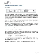
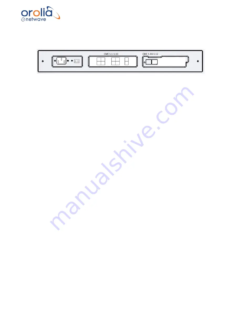
The Core Module integrates 3 functions from 3 independent modules being (from left to right in
figure above) power supply (UPS), data-switch, and CPU (central processing unit). These modules
are interconnected via a backplane within the enclosure.
The batteries required for the Uninterruptable Power Supply (the dedicated reserve power as per
IEC61996-1:2013) are included within this enclosure. The batteries are accessible by removing
the top cover of the unit. The batteries need to be replaced every two years.
5.2 Location and mounting
Determine the location of the CM, allowing space for wiring to enter the cabinet and batteries to
be replaced, as well as connectors to be accessible.
The Core Module may be placed on the bridge, within the bridge console or external thereto, or in
any technical room in the vicinity of the ship’s bridge provided adequate protection against
environmental conditions is provided as follows:
Temperature:
-15 to +55 C. (s70 C.)
Humidity:
max. 60% relative humidity (at 40 C.)
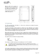
If the bulkhead-mounting enclosure is used, mount the bracket with your choice of bolts supplied
with the unit. Make sure the bracket is mounted with the slotted holes in the correct vertical
direction. Make sure it is horizontal.
Keep 50 mm of free space above the bracket to provide sufficient ventilation for this unit.
Summary of Contents for NW6000
Page 1: ......
Page 91: ...Page 91 191...
Page 92: ...Page 92 191...
Page 120: ...Page 120 191 Figure 17 4 2 Connection figure Digital Module 16 channels...
Page 121: ...Page 121 191 Figure 17 4 3 Connection figure Digital Module 24 channels...
Page 125: ...Page 125 191 Figure 18 4 2 Connection figure Analogue Module 8 channels...
Page 126: ...Page 126 191 Figure 18 4 3 Connection figure Analogue Module 12 channels...
Page 184: ...Page 184 191 Figure 5 8 1 Sample dataset playback...

