Page 113/ 191
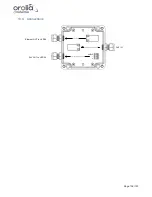
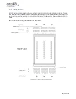
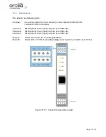
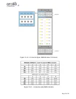
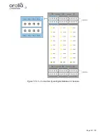
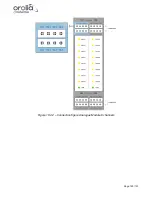
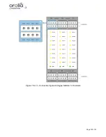
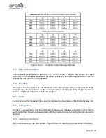
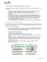
Figure 15.5.1 - Connection table Buscoupler
15.6 Data communications
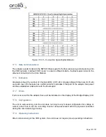
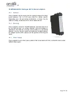
The adaptor has 1 x 10/100 TX PoE and three serial ports (IEC61162-2).
In default ‘VDR mode’ in order to offload its data - it relies on the ethernet connection to the core
module which must be IEC61162-450 compliant.
15.7 Indicators
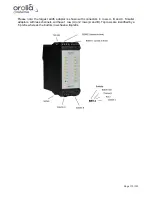
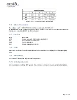
Led
Function
PWR
Power supply to DIN Busbar established
Link
Connected to Core Module
Data
Communications
PoE
Power Supply by PoE OK
15.8 Errors
If errors occur within the Buscoupler these will be indicated on the display of the Bridge Display
Unit.
15.9 Configuration
The unit does not require any manual configuration.
15.10 Operating instructions
After commissioning of the VDR system, this unit does not require (crew) operating instructions.
Summary of Contents for NW6000
Page 1: ......
Page 91: ...Page 91 191...
Page 92: ...Page 92 191...
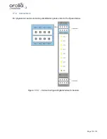
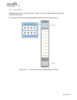
Page 120: ...Page 120 191 Figure 17 4 2 Connection figure Digital Module 16 channels...
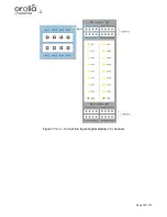
Page 121: ...Page 121 191 Figure 17 4 3 Connection figure Digital Module 24 channels...
Page 125: ...Page 125 191 Figure 18 4 2 Connection figure Analogue Module 8 channels...
Page 126: ...Page 126 191 Figure 18 4 3 Connection figure Analogue Module 12 channels...
Page 184: ...Page 184 191 Figure 5 8 1 Sample dataset playback...

