Page 128/ 191
19. Connecting to the VDR for configuration of the system
In the event the VDR is available in a fully operational state - the method to connect to the VDR
is as follows.
1. With an Ethernet cable, physically connect to the VDR (Core Module (CM); data port)
with any PC (or laptop, notebook) with a Windows Operating System.
2. Change the IP address of the PC to be within the IP-range of the VDR and set it to
172.16.8.199
.
3. Open a web-browser and go to the URL
172.16.8.2 or https://nw6000.orolia.local
.
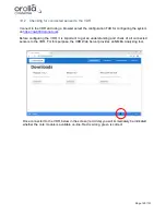
4. If necessary, download & install the Player & Conversion Software as well as the Manual
for these from the VDR to the PC. The VDR Playback software can also be obtained
from the Netwave Systems extranet. For login details, please check with Netwave
Systems (service@netwavesystems.com).
5. Run the Playback software and select the configuration TAB for configuring the system.
19.1 Physically connecting to the VDR
The VDR’s Ethernet ports on the Core Module are auto-sensing and you should not have to
change your Ethernet cable, however, if you encounter problems obtaining access to the VDR
Core Module, check the following:
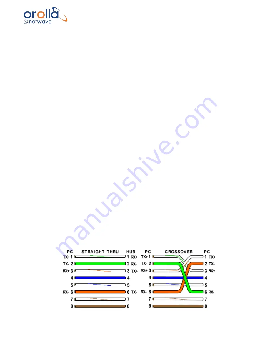
a. The Ethernet cable between the PC (Laptop, notebook computer) and the CM should be
a standard, readymade patch-type cable to overcome potential straight-thru vs. crossover
Ethernet cabling issues. Change the cable if required.
-
A straight-thru cable has identical ends.
-
A crossover cable has different ends.
-
A straight-thru is used as a patch cord in Ethernet connections.
-
A crossover is used to connect two Ethernet devices without a hub or for connecting two
hubs.
-
A crossover has one end with the Orange set of wires switched with the Green set.
-
Odd numbered pins are always striped, even numbered pins are always solid colored.
-
Looking at the RJ-45 with the clip facing away from you, Brown is always on the right,
and pin 1 is on the left.
-
No more than 1/2" of the Ethernet cable should be untwisted otherwise it will be
susceptible to crosstalk.
Summary of Contents for NW6000
Page 1: ......
Page 91: ...Page 91 191...
Page 92: ...Page 92 191...
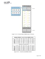
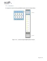
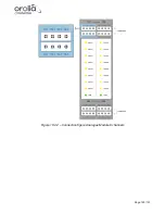
Page 120: ...Page 120 191 Figure 17 4 2 Connection figure Digital Module 16 channels...
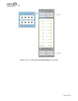
Page 121: ...Page 121 191 Figure 17 4 3 Connection figure Digital Module 24 channels...
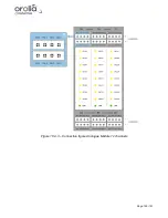
Page 125: ...Page 125 191 Figure 18 4 2 Connection figure Analogue Module 8 channels...
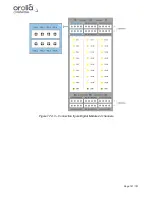
Page 126: ...Page 126 191 Figure 18 4 3 Connection figure Analogue Module 12 channels...
Page 184: ...Page 184 191 Figure 5 8 1 Sample dataset playback...

