Page 82/ 191
To fine tune the Gain and Offset using the histogram of Red, Green, and Blue icons:
1.
Click on the histogram icon to be adjusted.
2.
Drag the icon and observe changes in the Capture window image.
3.
When the adjustment is finished, release the icon.
4.
The new value is displayed in the corresponding scroll box beneath the histogram.
(The range is 0-255).
5.
Repeat the process for each of the controls in the histogram until the captured image is
satisfactory.
For example, click the Red Offset icon in the histogram and drag it up or down to adjust the Red
Offset value.
To fine tune the Gain and Offset Red, Green, and Blue separately, using scroll boxes and the
Ref: selection:
1. Click on the scroll box for the value to be adjusted.
2. Set the Gain or Offset to the new value. (The range is 0 to 255).
3. Continue adjusting values until the image in the Capture window is fine tuned.
To fine tune the Gain and Offset using the
Master
Gain and Offset scroll buttons:
Adjusting Gain stretches the image vertically in the Capture window.
1. Click on the Master Gain scroll button to adjust the Gain of the entire image - instead of
the individual Red, Green and Blue values (the range is 0 to 255).
2. Click on the Master Offset scroll button to adjust the Offset of the entire image - instead
of the individual Red, Green and Blue values (the range is 0 to 255). Adjusting the offset
shifts the image up and down in the Capture window.
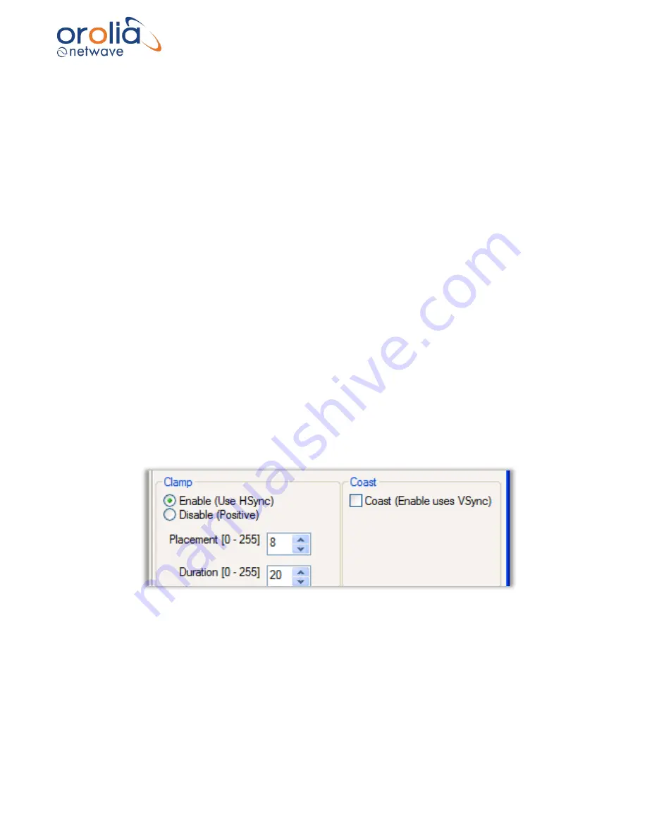
Figure 10.23.2
– Clamp and Coast sections of the Adjustments tab page
10.24 Clamp
At the lower left of the Adjustments page is the
Clamp
section. It allows the installer to enable or
disable the video capture HSync signal default. The Clamp controls are necessary so the installer
can enable VSYNC signal capture if there is no HSYNC signal.
▪
Enable (Use HSYNC) check button
: In the absence of a VSYNC signal, the video capture
circuitry will use the HSYNC signal. This is the Clamp command default setting.
Summary of Contents for NW6000
Page 1: ......
Page 91: ...Page 91 191...
Page 92: ...Page 92 191...
Page 120: ...Page 120 191 Figure 17 4 2 Connection figure Digital Module 16 channels...
Page 121: ...Page 121 191 Figure 17 4 3 Connection figure Digital Module 24 channels...
Page 125: ...Page 125 191 Figure 18 4 2 Connection figure Analogue Module 8 channels...
Page 126: ...Page 126 191 Figure 18 4 3 Connection figure Analogue Module 12 channels...
Page 184: ...Page 184 191 Figure 5 8 1 Sample dataset playback...


