Page 96/ 191
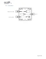
11.4.2 Wire schematic Junction box
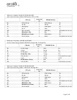
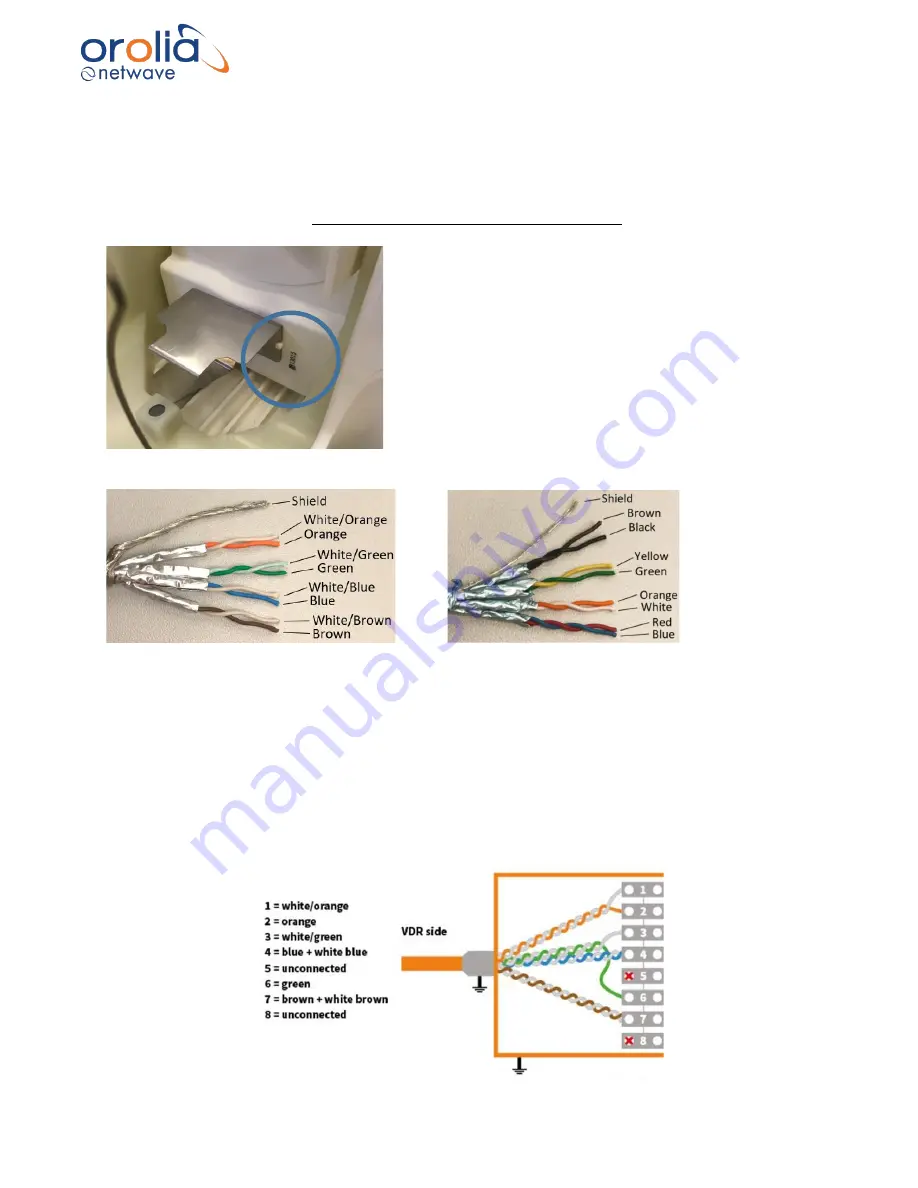
There are 2 different cable types of the TRON 40VDR with 3 different cable connections (2 for cable type
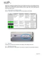
1, 1 for cable type 2). Identify the serial number of the docking module and identify the cable type of TRON
40VDR to determine the applicable wire diagram. The serial number of the docking module can be found
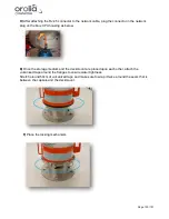
as indicated on picture below, this is not the serial number of the VDR EPIRB.
Cable type 1 TRON 40VDR:
Cable type 2 TRON 40VDR:
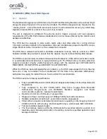
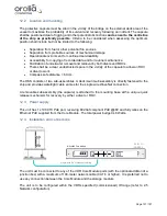
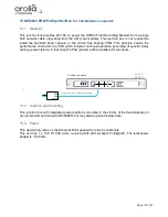
Connect the TRON 40VDR to the VDR via the junction box as further described.
Notes:
- Connect inside the junction box on the VDR side White/blue and Blue wires together.
- Connect inside the junction box on the VDR side the White/brown and Brown wires together.
- Note that exchanging the DC + and DC
–
will not cause any damage, but the TRON 40VDR will not
work.
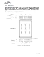
Connections NW6000 VDR side:
Summary of Contents for NW6000
Page 1: ......
Page 91: ...Page 91 191...
Page 92: ...Page 92 191...
Page 120: ...Page 120 191 Figure 17 4 2 Connection figure Digital Module 16 channels...
Page 121: ...Page 121 191 Figure 17 4 3 Connection figure Digital Module 24 channels...
Page 125: ...Page 125 191 Figure 18 4 2 Connection figure Analogue Module 8 channels...
Page 126: ...Page 126 191 Figure 18 4 3 Connection figure Analogue Module 12 channels...
Page 184: ...Page 184 191 Figure 5 8 1 Sample dataset playback...


